Plant roomHome Unfolded

Plant-room evidence

Photo index

Every source JPEG, grouped by the equipment or observation it supports.
76of 76 photos
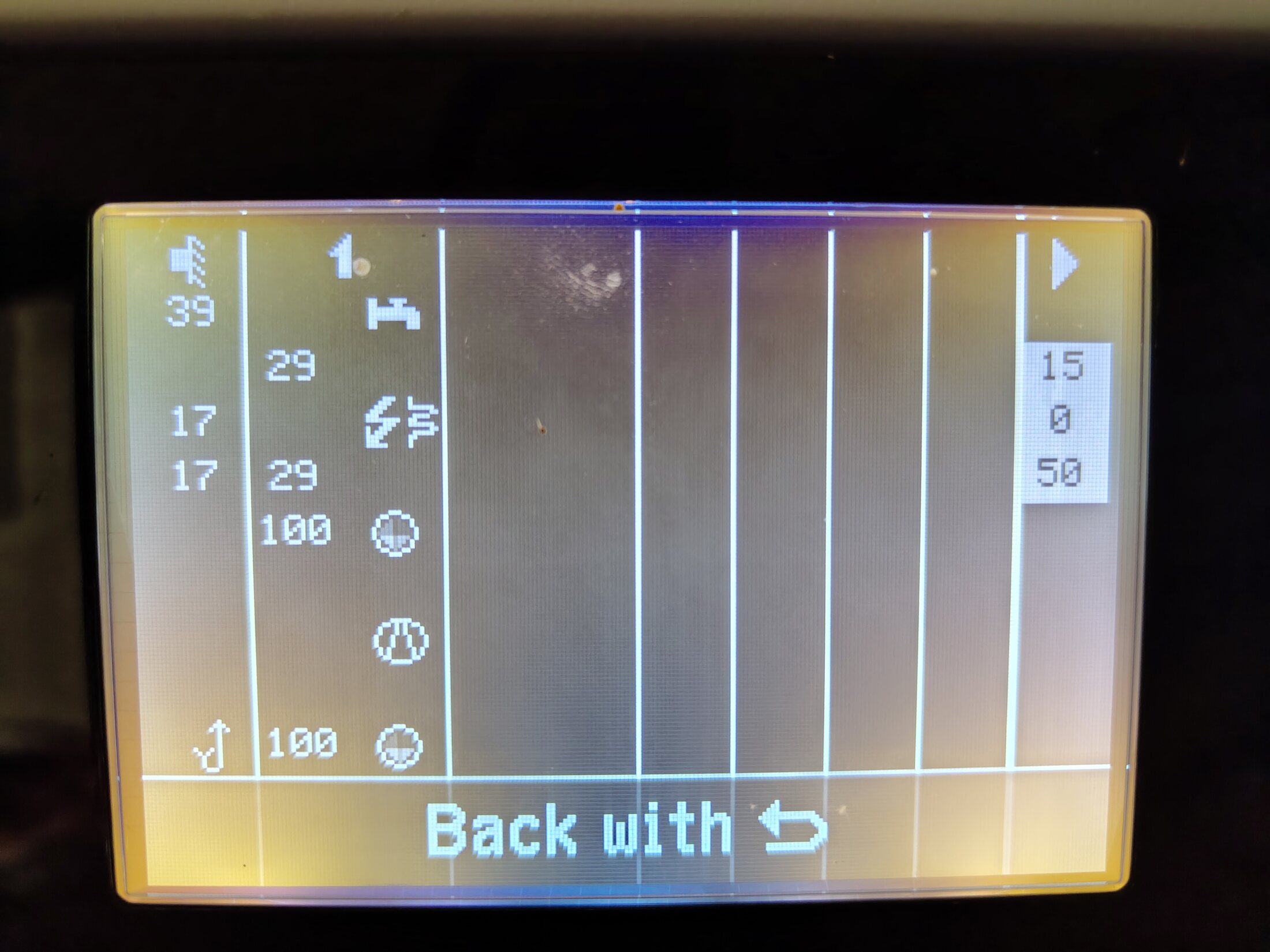
Hydraulic overview during natural cooling. Front control panel.ConfirmedOpen full image ↗
IMG_20260623_162614425.jpg

Heat-pump controller · 23 June

Hydraulic overview during natural cooling

View
Front control panel
Evidence
Controller display directly shows operating values and pump commands.
Confidence
high
Full image
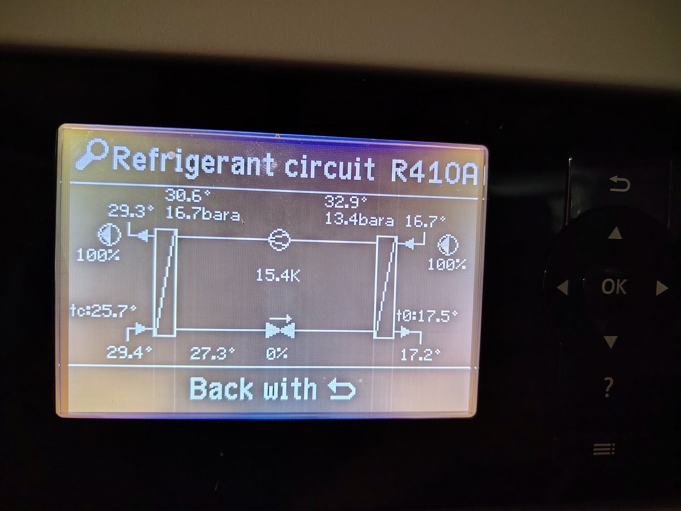
Refrigerant-circuit diagnostic screen. Front control panel.ConfirmedOpen full image ↗
IMG_20260623_162642097.jpg

Heat-pump controller · 23 June

Refrigerant-circuit diagnostic screen

View
Front control panel
Evidence
Direct controller display; compressor-state interpretation belongs with the recorded timestamp.
Confidence
high
Full image
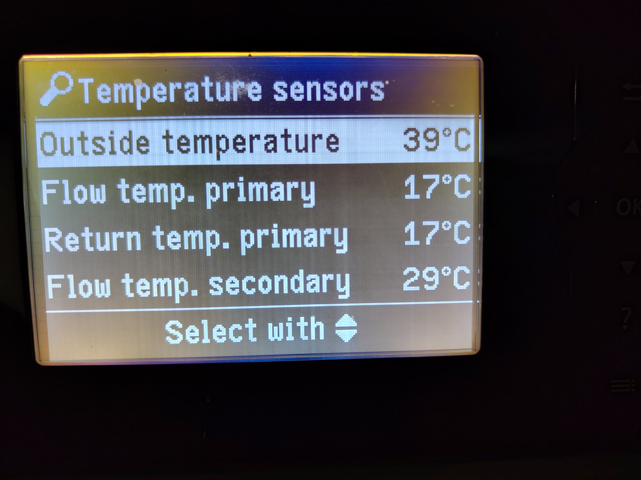
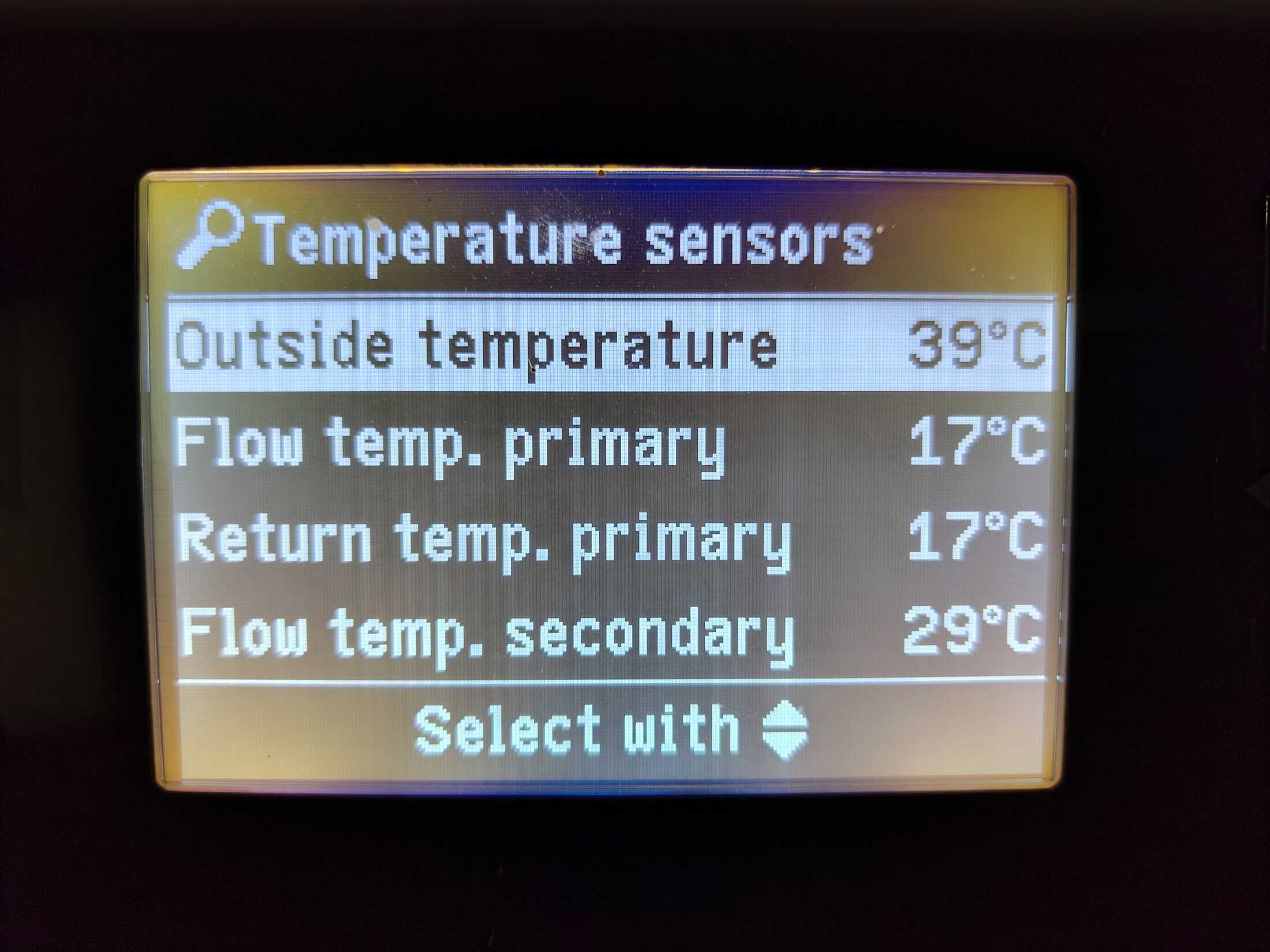
Primary and secondary temperature sensors. Front control panel.ConfirmedOpen full image ↗
IMG_20260623_162733852.jpg

Heat-pump controller · 23 June

Primary and secondary temperature sensors

View
Front control panel
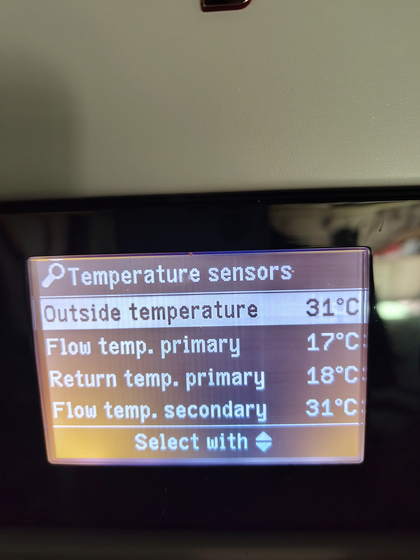
Evidence
Direct display of outside, primary flow/return and secondary flow temperatures.
Confidence
high
Full image
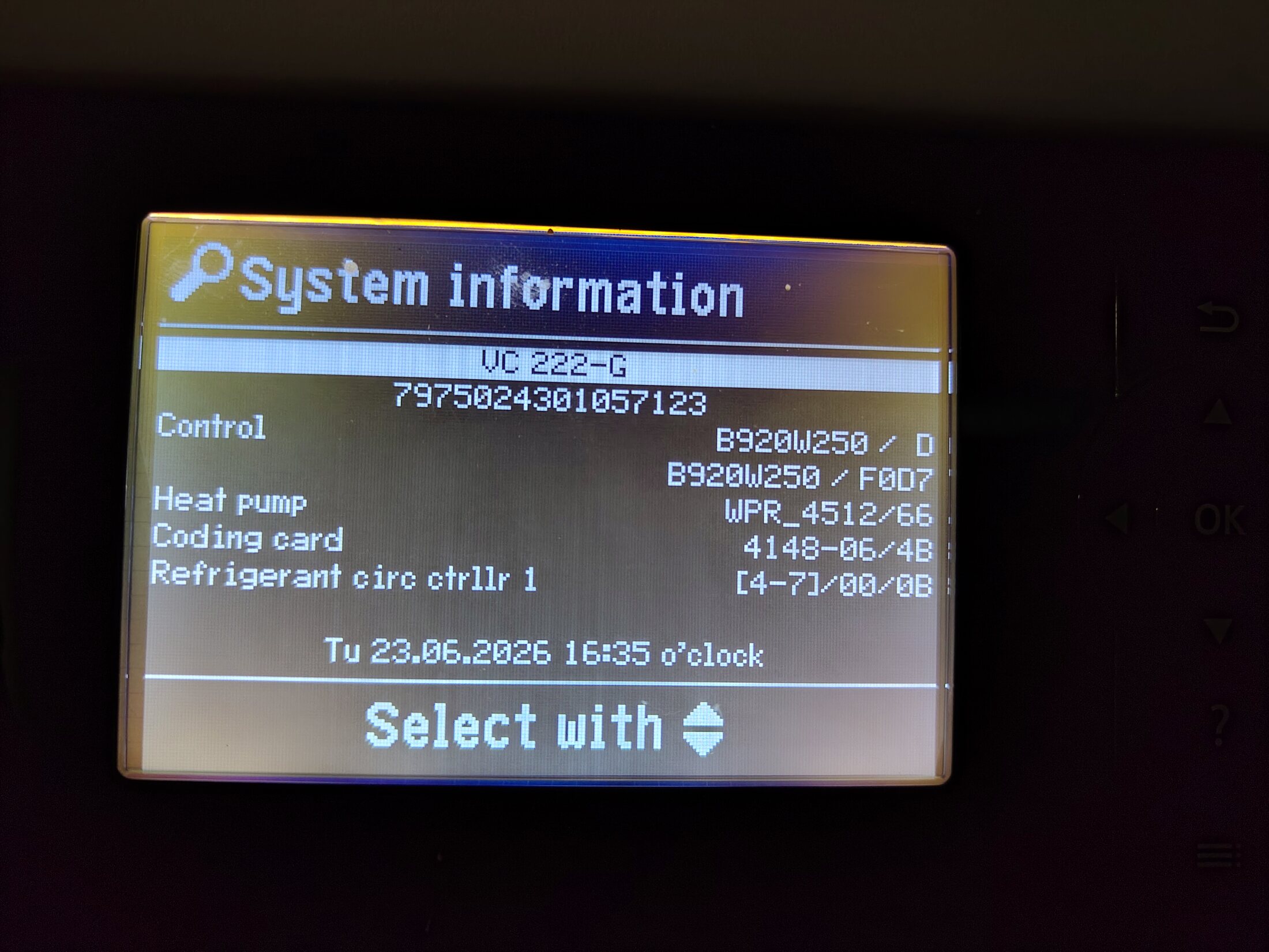
System information screen. Front control panel.ConfirmedOpen full image ↗
IMG_20260623_162754959.jpg

Heat-pump controller · 23 June

System information screen

View
Front control panel
Evidence
Direct controller identification and firmware/system information.
Confidence
high
Full image
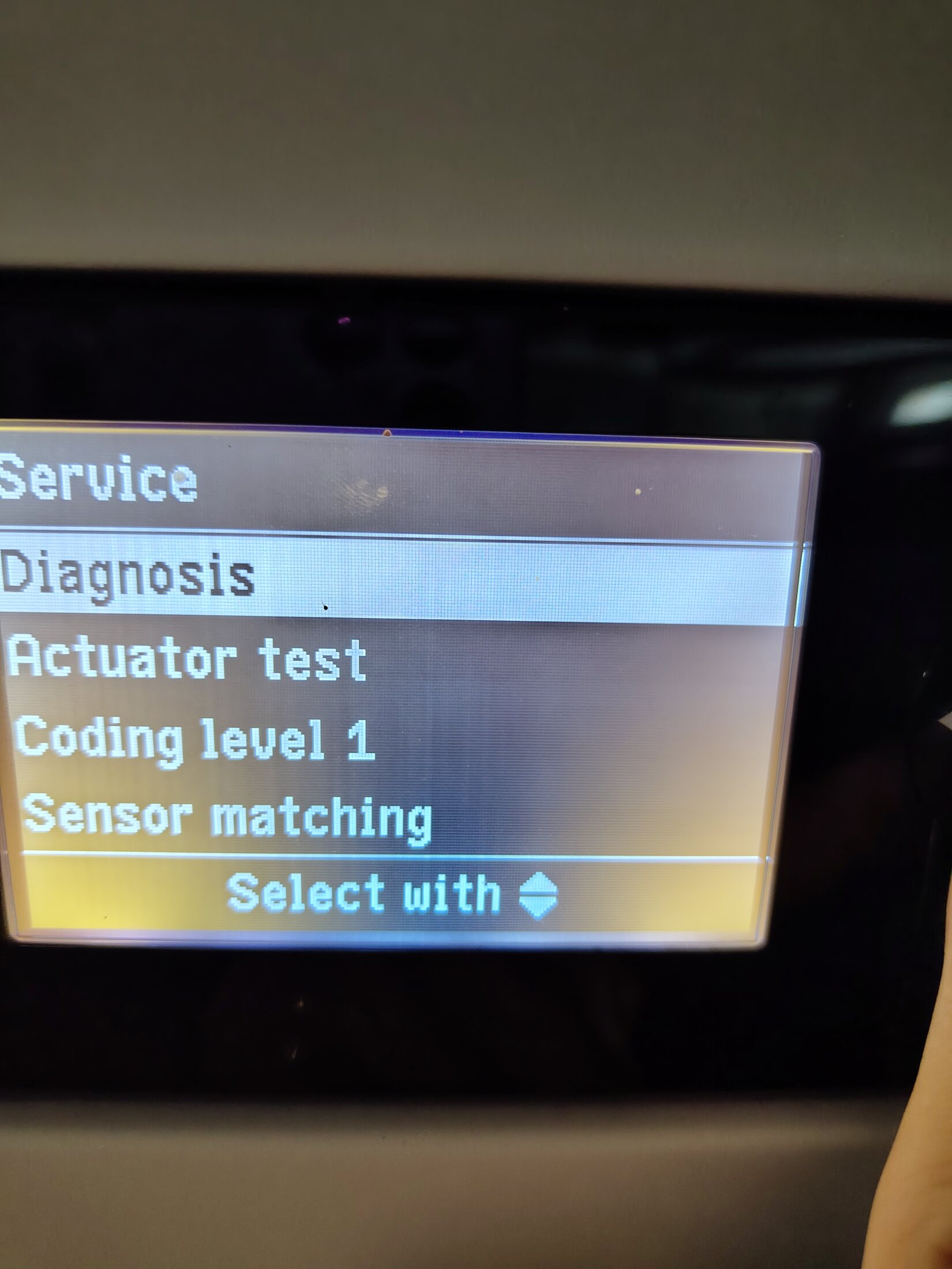
Service and diagnosis menu. Front control panel.Visible, route openOpen full image ↗
IMG_20260623_162908182.jpg

Heat-pump controller · 23 June

Service and diagnosis menu

View
Front control panel
Evidence
Navigation context for the neighbouring diagnostic photographs.
Confidence
high
Full image
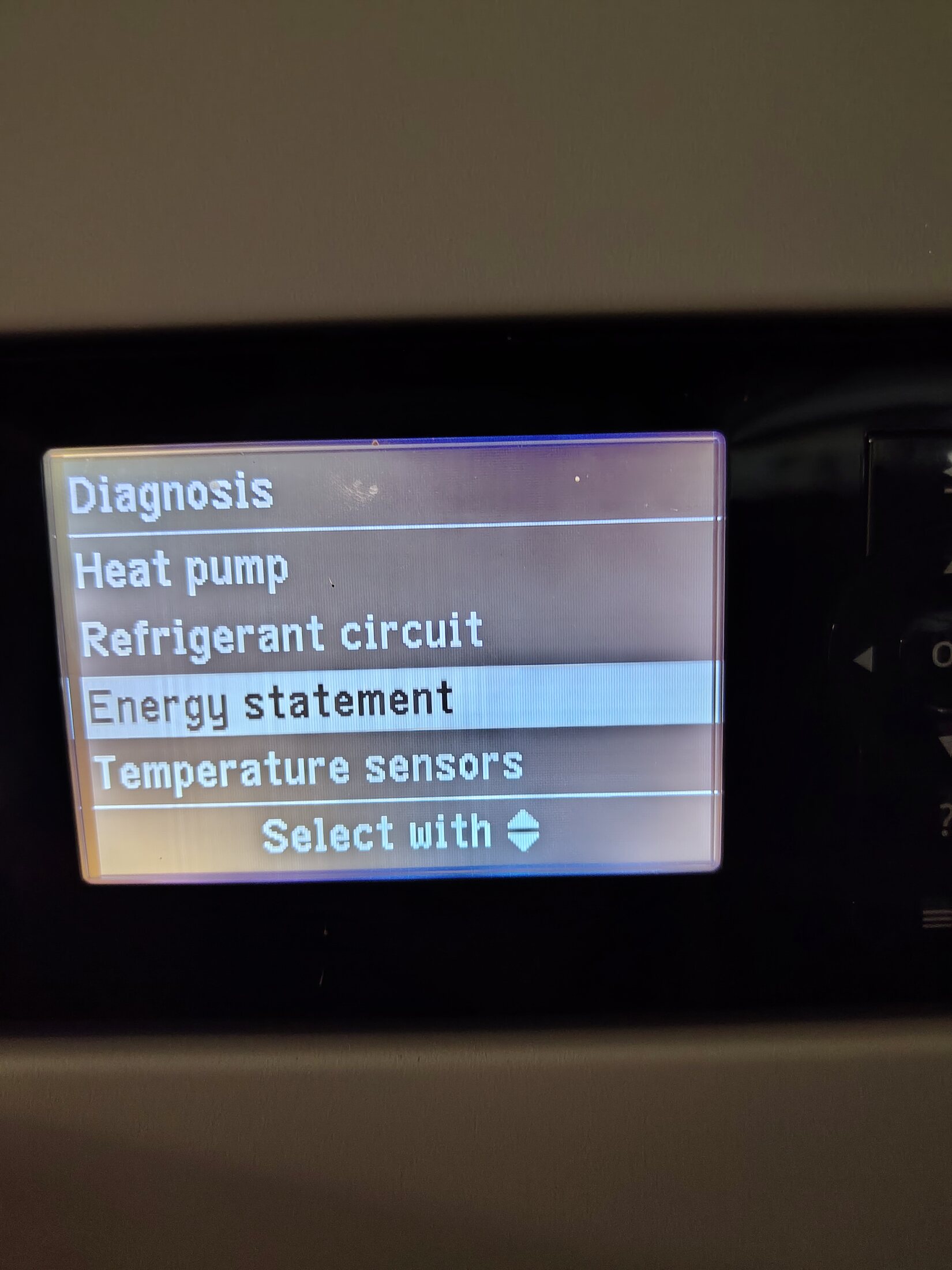
Diagnosis menu. Front control panel.Visible, route openOpen full image ↗
IMG_20260623_163006510.jpg

Heat-pump controller · 23 June

Diagnosis menu

View
Front control panel
Evidence
Navigation context for energy, refrigerant and temperature screens.
Confidence
high
Full image
Primary and secondary temperature sensors · second view. Front control panel.ConfirmedOpen full image ↗
IMG_20260623_163203558.jpg

Heat-pump controller · 23 June

Primary and secondary temperature sensors · second view

View
Front control panel
Evidence
Direct display; useful duplicate for legibility and timestamp sequence.
Confidence
high
Full image
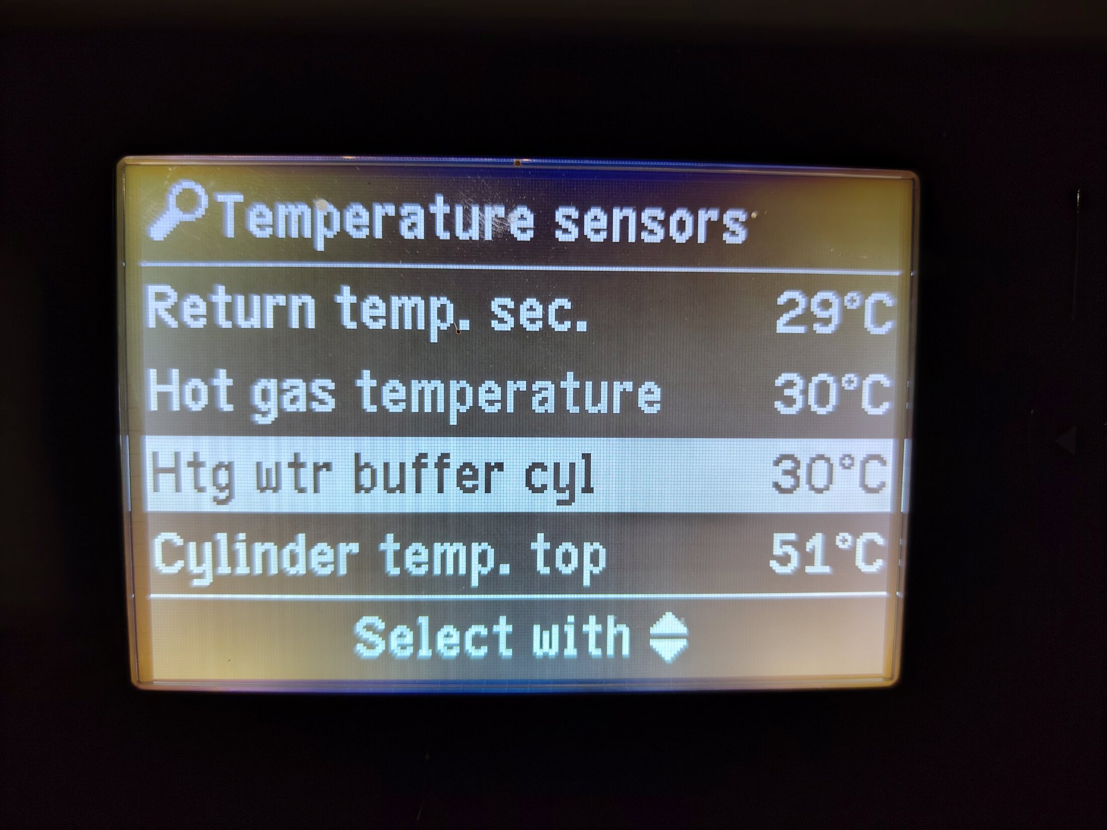
Secondary return, hot-gas and cylinder temperatures. Front control panel.ConfirmedOpen full image ↗
IMG_20260623_163217075.jpg

Heat-pump controller · 23 June

Secondary return, hot-gas and cylinder temperatures

View
Front control panel
Evidence
Direct controller display.
Confidence
high
Full image
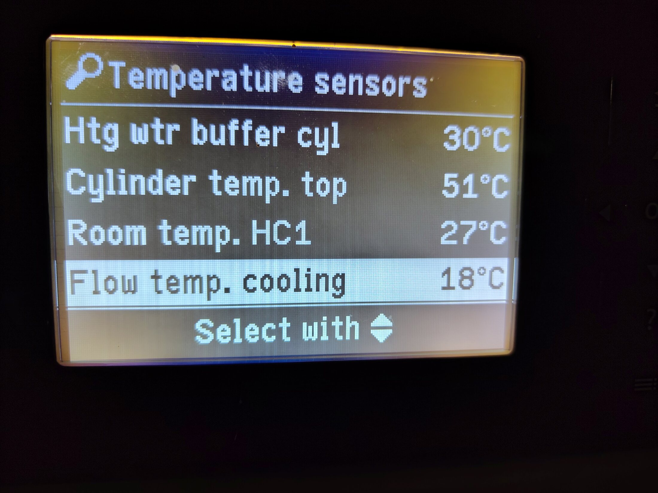
Actual cooling-flow temperature. WO1C service diagnostics · temperature sensors.ConfirmedOpen full image ↗
IMG_20260623_163223419.jpg

Heat-pump controller · 23 June

Actual cooling-flow temperature

View
WO1C service diagnostics · temperature sensors
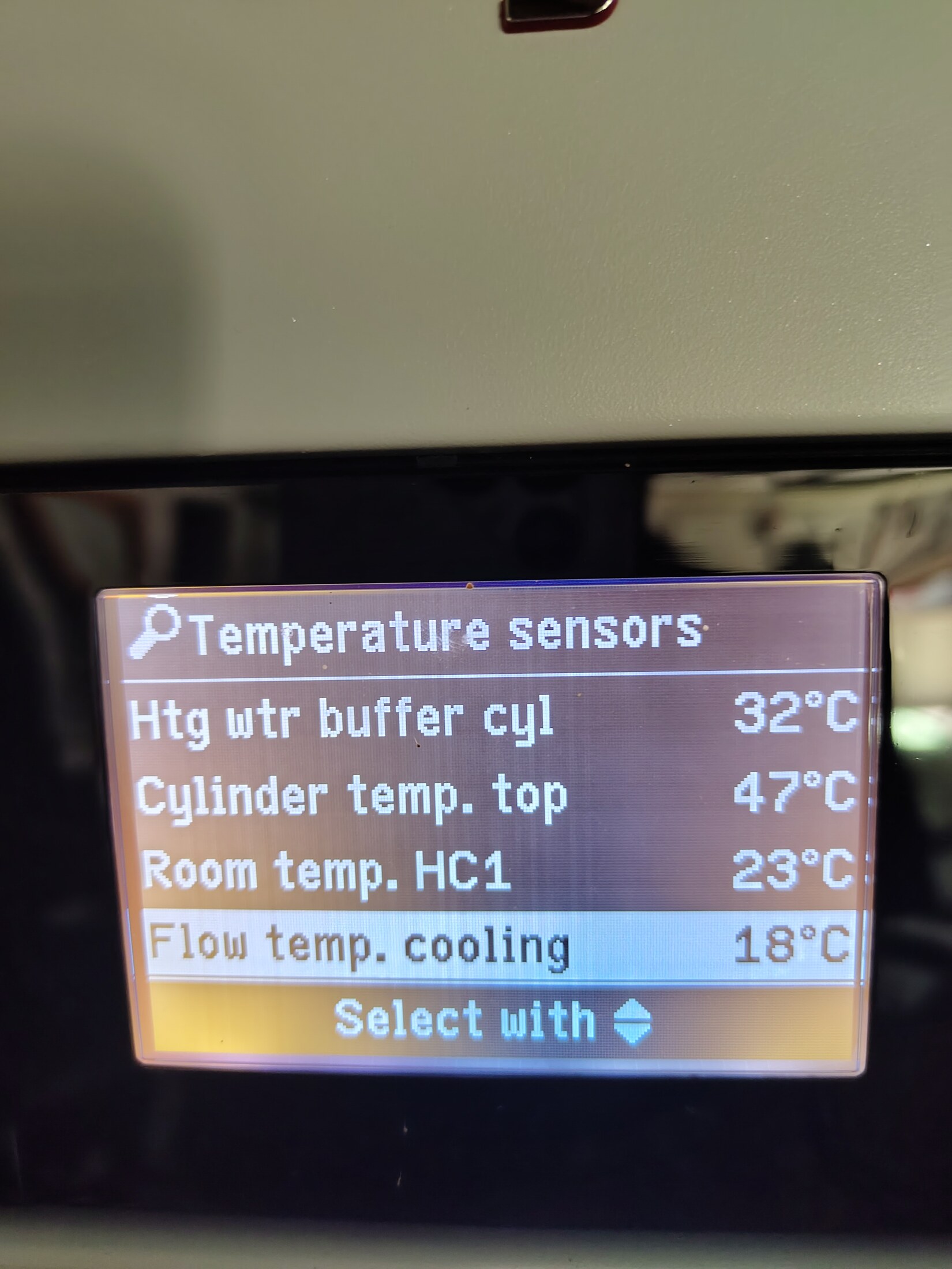
Evidence
The Temperature sensors screen explicitly reports `Flow temp. cooling 18 °C`. This is the controller's actual cooling-supply measurement, independent of the separate 18 °C circuit target exposed by ViCare.
Confidence
high
Full image
Hydraulic overview · second view. Front control panel.ConfirmedOpen full image ↗
IMG_20260623_163419320.jpg

Heat-pump controller · 23 June

Hydraulic overview · second view

View
Front control panel
Evidence
Direct controller display; duplicate operating snapshot.
Confidence
high
Full image
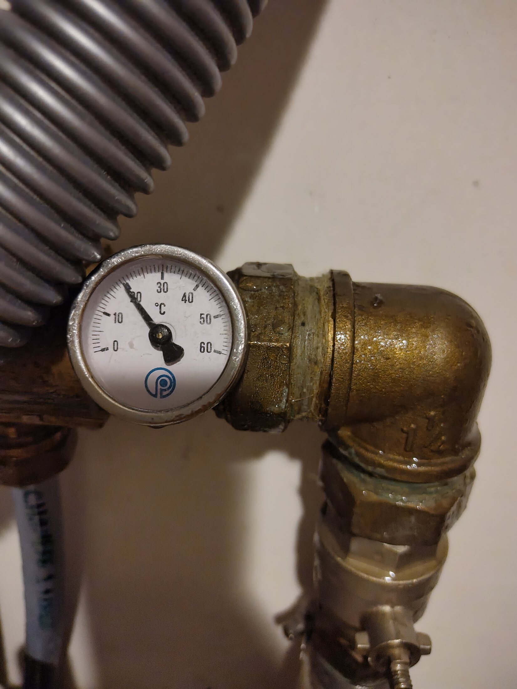
Manifold dial thermometer · end fitting. Upper-floor manifold · close-up.Needs reviewOpen full image ↗
IMG_20260623_191006187.jpg

Upper-floor manifold · 23 June

Manifold dial thermometer · end fitting

View
Upper-floor manifold · close-up
Evidence
Dial reading is visible; exact supply/return assignment still needs a physical marker.
Confidence
medium
Full image
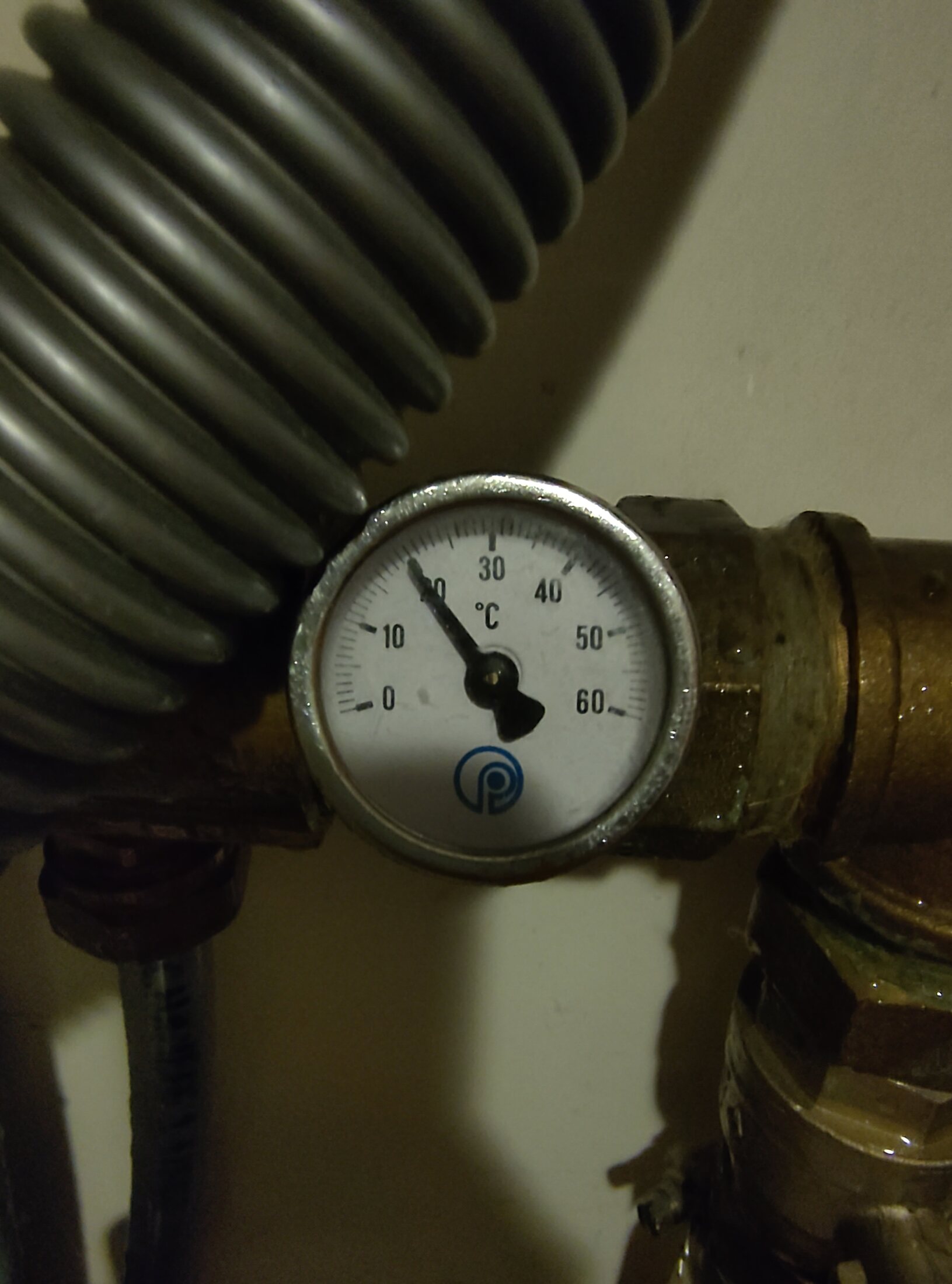
Manifold dial thermometer · pipe view. Upper-floor manifold · close-up.Needs reviewOpen full image ↗
IMG_20260623_191011983.jpg

Upper-floor manifold · 23 June

Manifold dial thermometer · pipe view

View
Upper-floor manifold · close-up
Evidence
Dial reading is visible; exact header assignment is not encoded in the image.
Confidence
medium
Full image
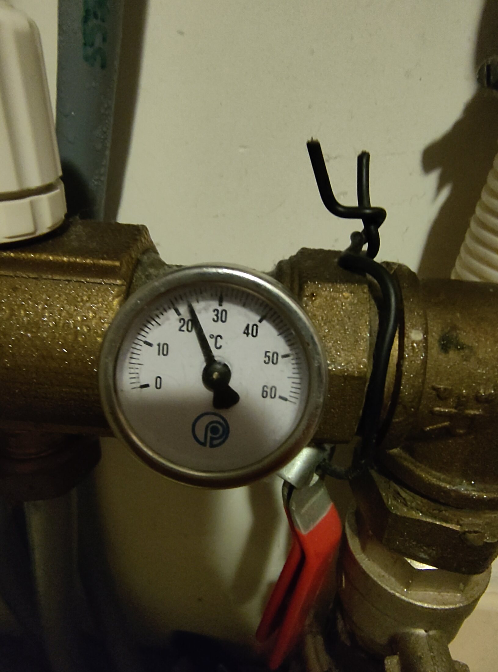
Manifold dial thermometer · valve view. Upper-floor manifold · close-up.Needs reviewOpen full image ↗
IMG_20260623_191018376.jpg

Upper-floor manifold · 23 June

Manifold dial thermometer · valve view

View
Upper-floor manifold · close-up
Evidence
Dial reading and adjacent valve are visible; flow direction remains unmarked.
Confidence
medium
Full image
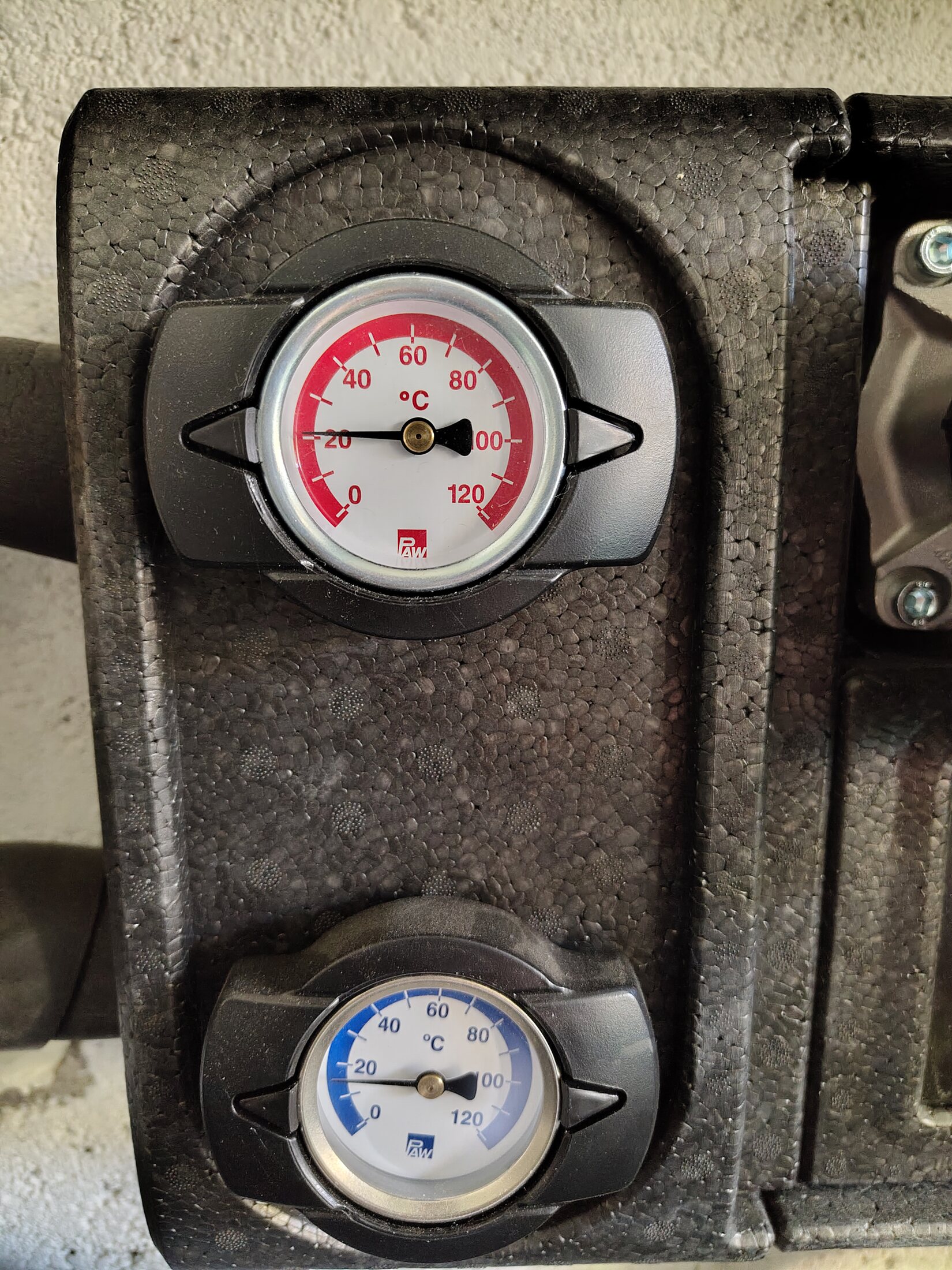
Red and blue dial thermometers. Front close-up.Visible, route openOpen full image ↗
IMG_20260814_094500302.jpg

Secondary pump / mixer group

Red and blue dial thermometers

View
Front close-up
Evidence
Direct component view. Colours do not establish installation-specific flow direction.
Confidence
high
Full image
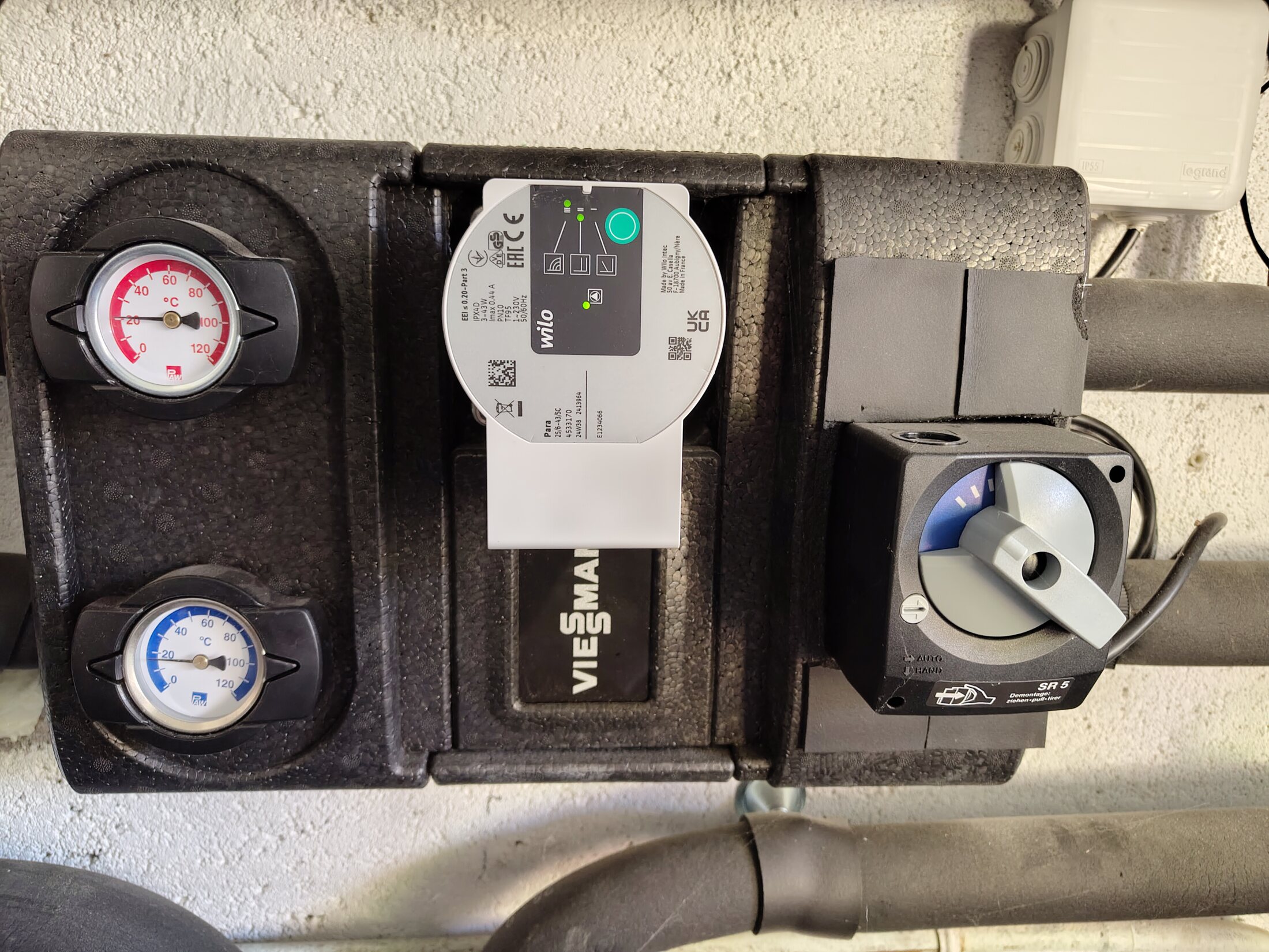
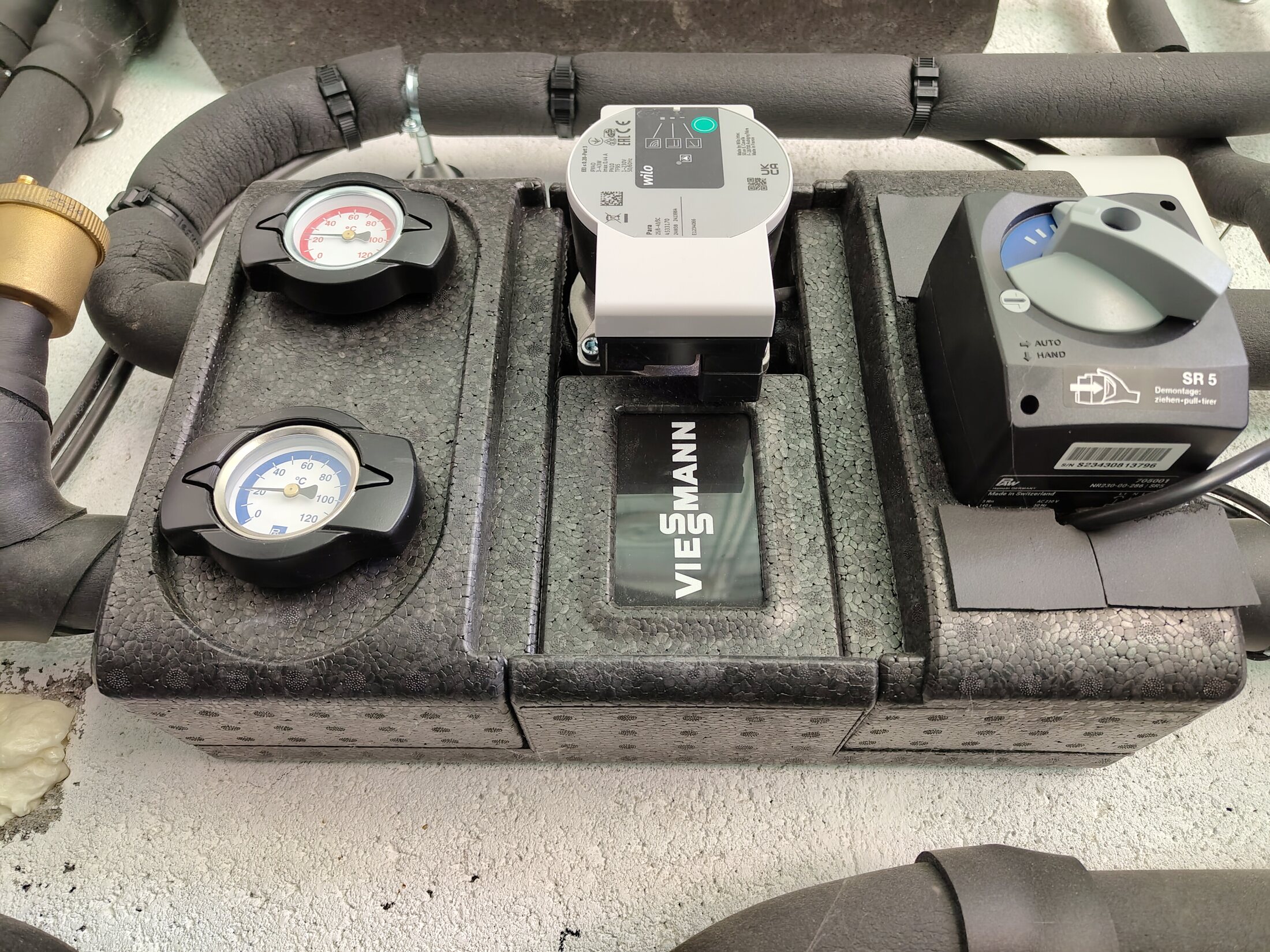
Wilo Para secondary circulator. Front close-up.ConfirmedP2 · useful detailOpen full image ↗
IMG_20260814_094505202.jpg

Secondary pump / mixer group

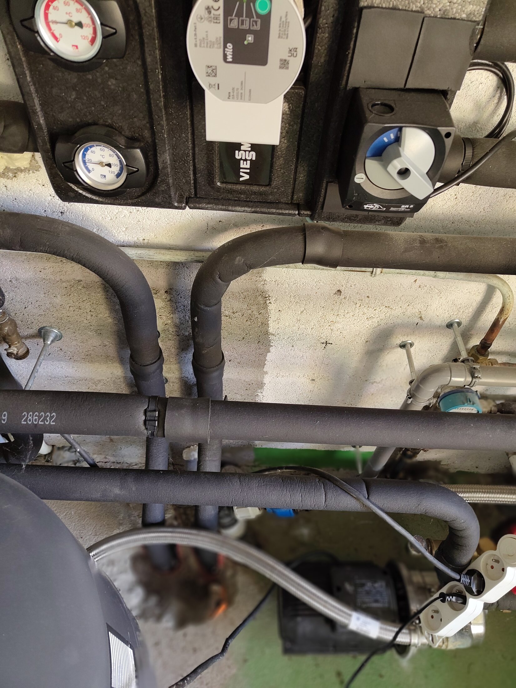
Wilo Para secondary circulator

View
Front close-up
Evidence
Manufacturer/model family is readable on the pump face. The sharper companion IMG_20260814_151850299.jpg records Δp-c curve III; neither image provides volumetric flow.
Verify
Recheck whether Δp-c curve III persists during heating and natural cooling, and measure actual flow separately.
Confidence
high
Full image
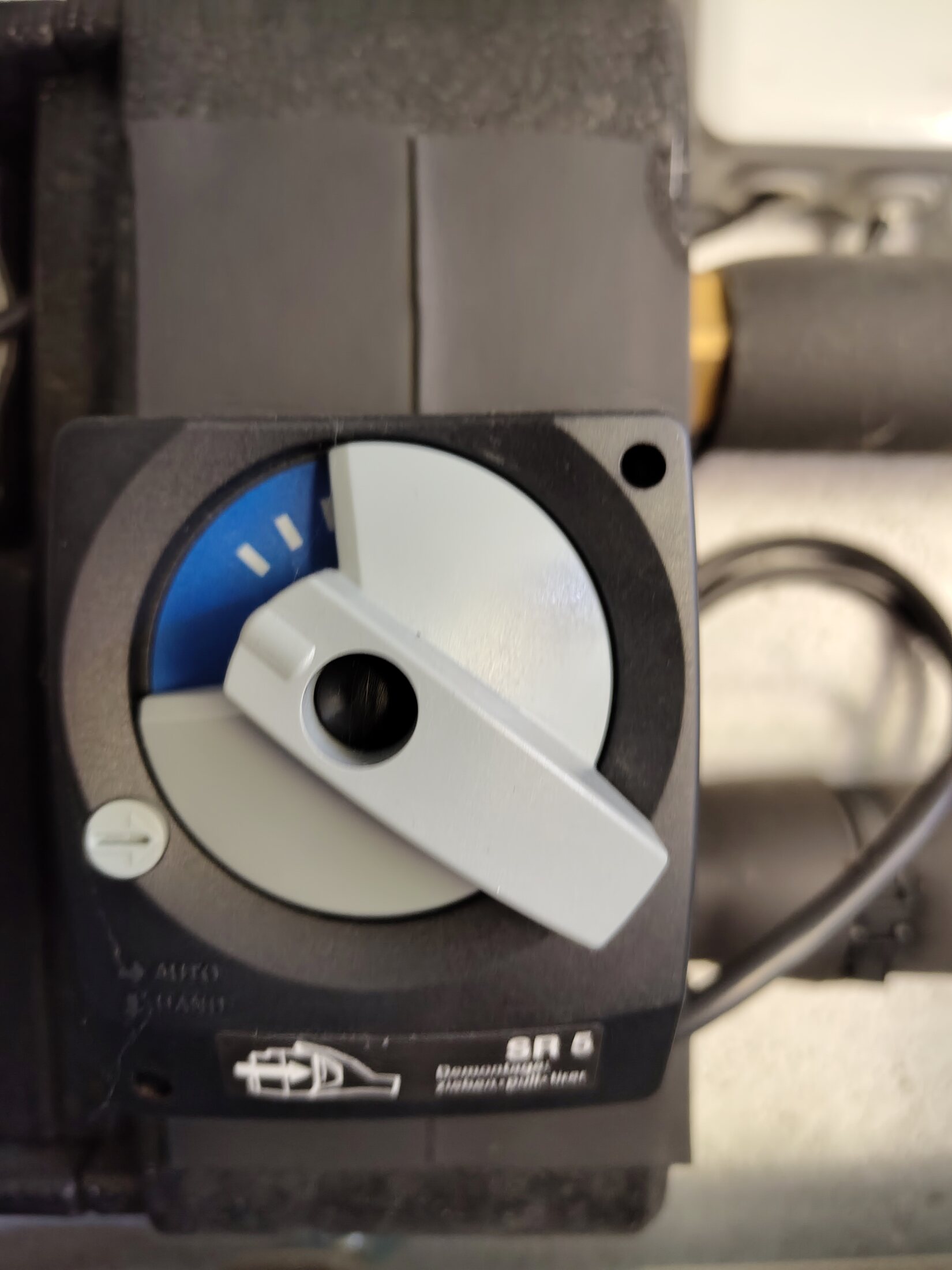
PAW / Viessmann SR 5 mixer actuator. Front close-up.ConfirmedP2 · useful detailOpen full image ↗
IMG_20260814_094511456.jpg

Secondary pump / mixer group

PAW / Viessmann SR 5 mixer actuator

View
Front close-up
Evidence
SR 5 label and actuator position are visible.
Verify
Record the actuator setting and trace its controlled valve ports without inferring flow direction from thermometer colours.
Confidence
high
Full image
Secondary-group side label. Left edge close-up.Needs reviewP2 · useful detailOpen full image ↗
IMG_20260814_094516080.jpg

Secondary pump / mixer group

Secondary-group side label

View
Left edge close-up
Evidence
Label is photographed obliquely; transcription should be checked against a straight-on image.
Verify
Take a square, sharp label photograph so the complete product and configuration text can be transcribed.
Confidence
medium
Full image
Earlier overview of the complete pump / mixer group. Front overview.ConfirmedOpen full image ↗
IMG_20260814_094520085.jpg

Secondary pump / mixer group

Earlier overview of the complete pump / mixer group

View
Front overview
Evidence
Shows both thermometers, Wilo circulator and SR 5 actuator in context.
Confidence
high
Full image
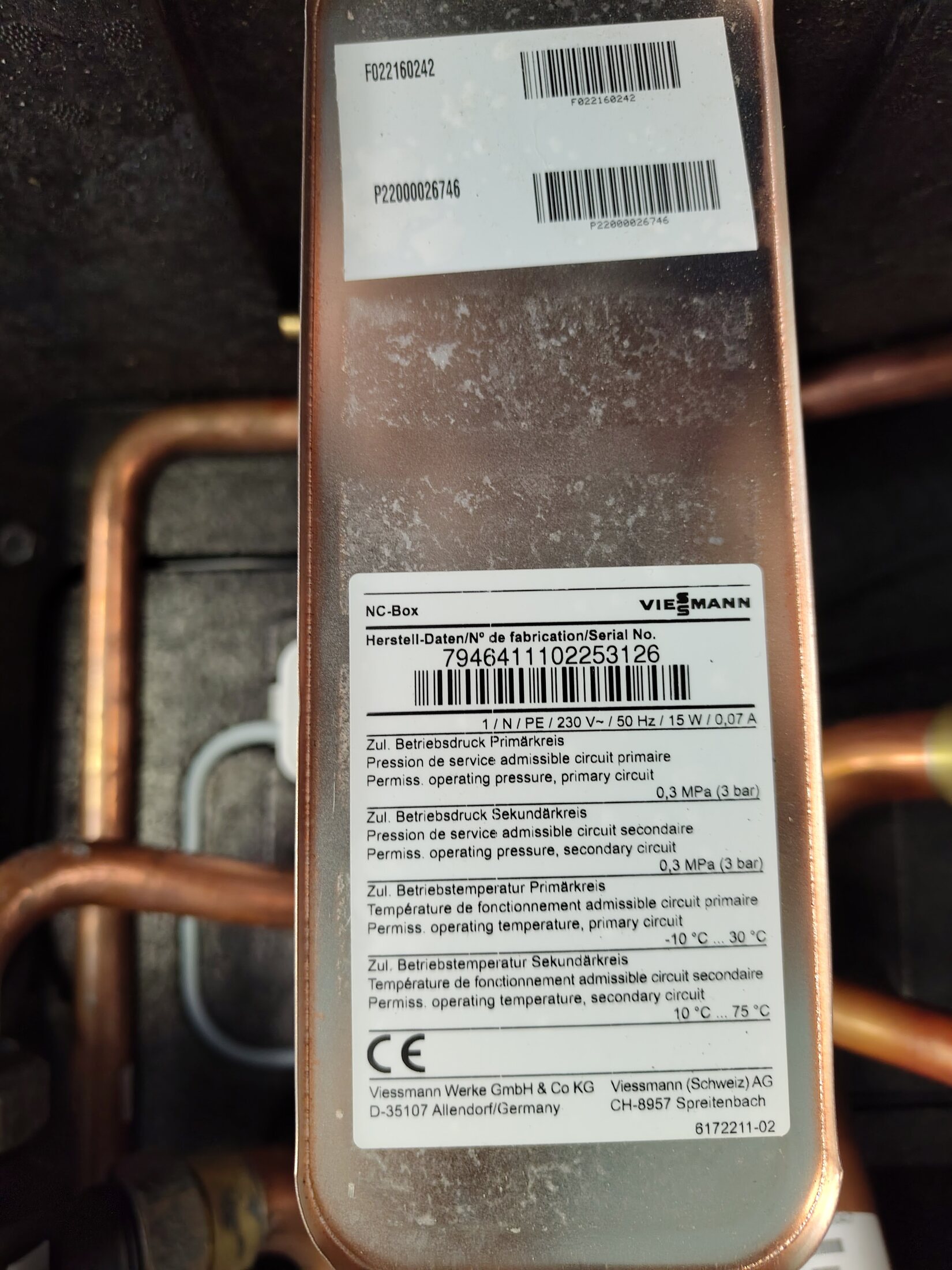
NC-Box plate heat-exchanger label. Open enclosure · centre.ConfirmedOpen full image ↗
IMG_20260814_094524806.jpg

NC-Box interior

NC-Box plate heat-exchanger label

View
Open enclosure · centre
Evidence
Manufacturer label and adjacent copperwork are visible.
Confidence
high
Full image
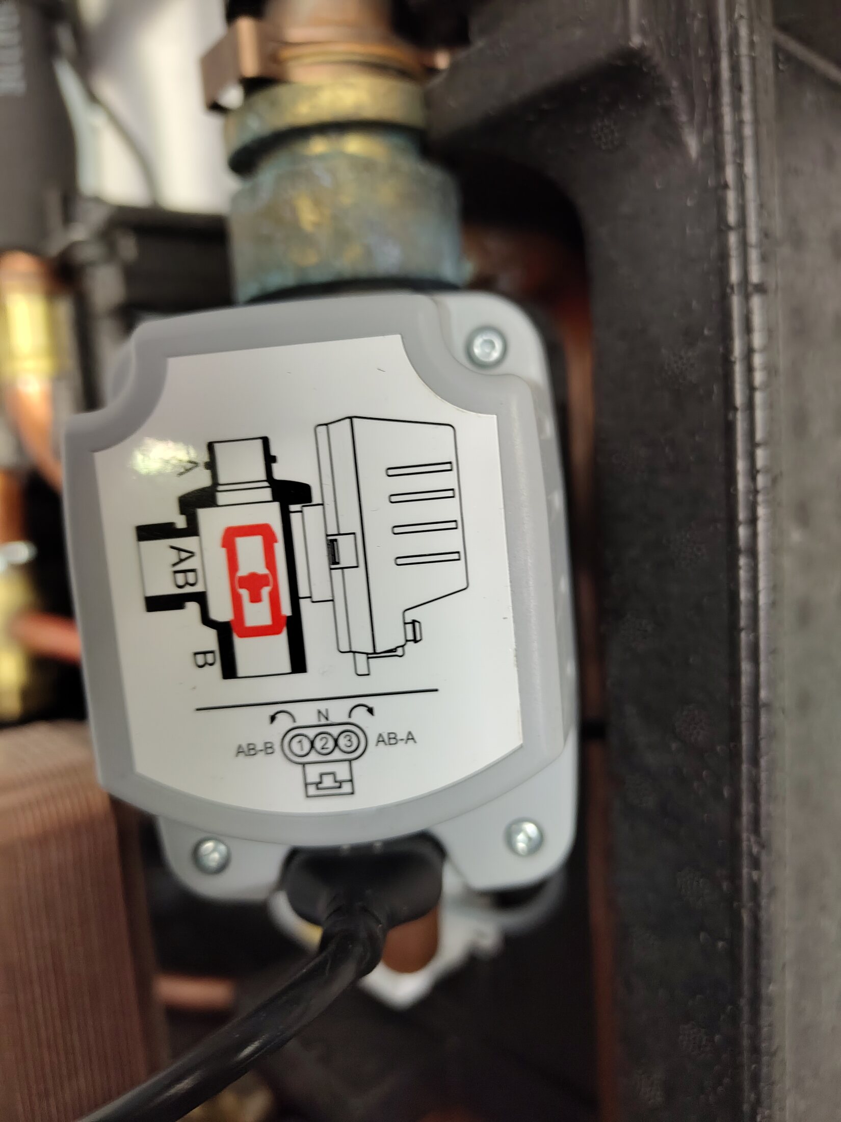
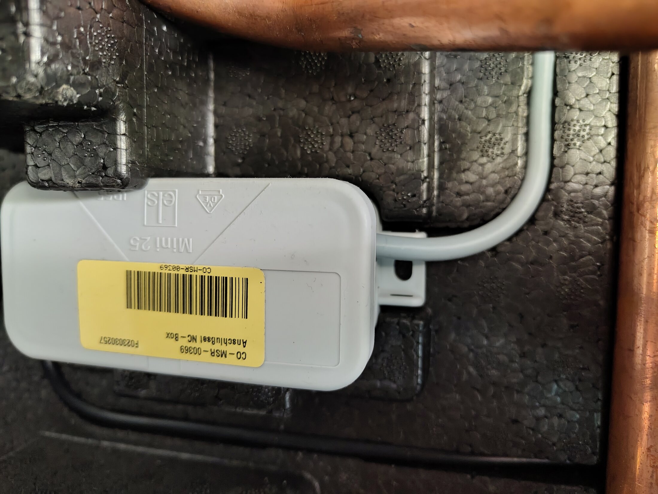
Motorized changeover valve actuator. Open enclosure · lower-left.ConfirmedOpen full image ↗
IMG_20260814_094529577.jpg

NC-Box interior

Motorized changeover valve actuator

View
Open enclosure · lower-left
Evidence
Actuator markings and A/B/AB valve diagram are visible.
Confidence
high
Full image
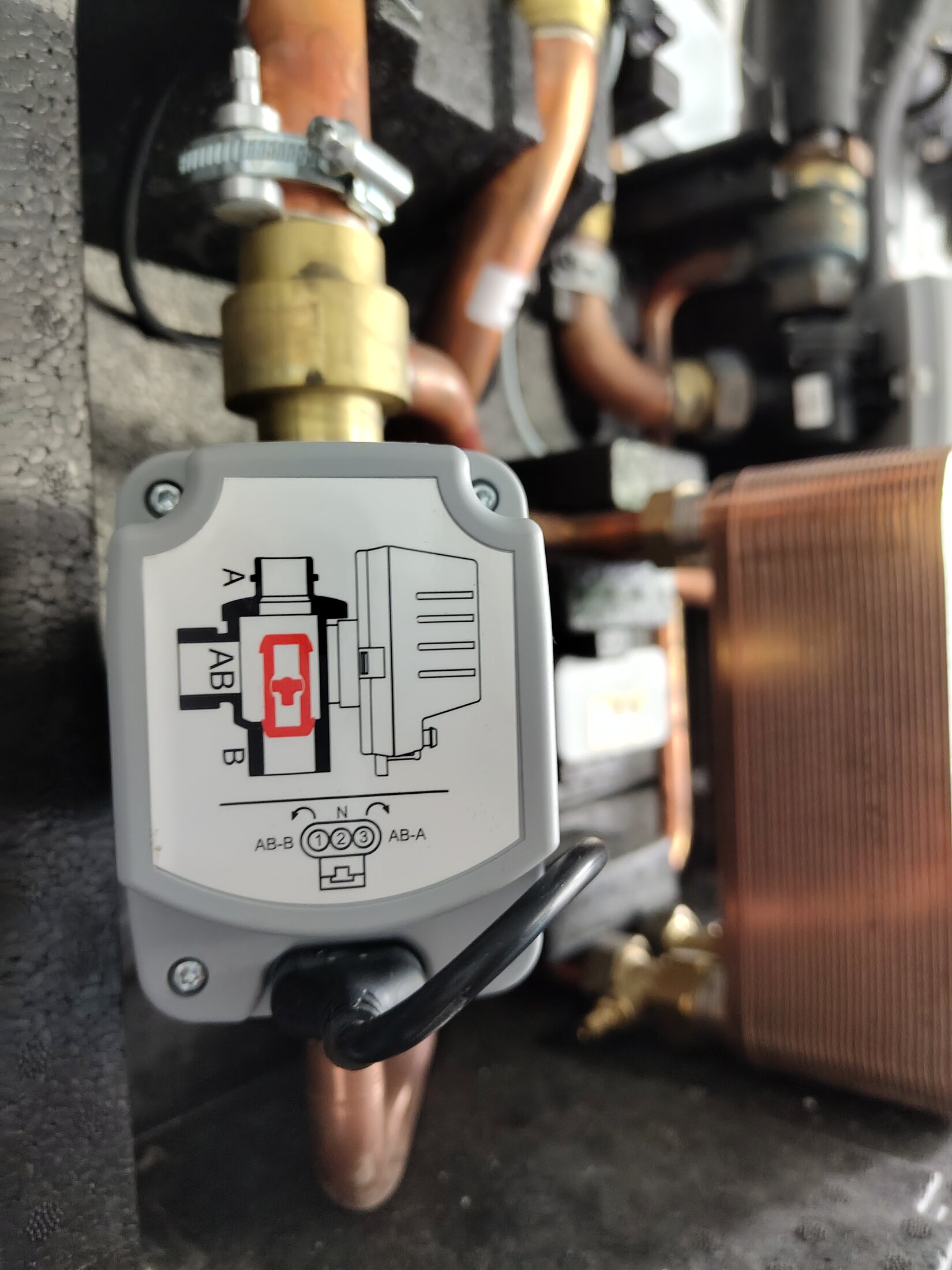
Second motorized changeover valve actuator. Open enclosure · upper-right.ConfirmedOpen full image ↗
IMG_20260814_094534168.jpg

NC-Box interior

Second motorized changeover valve actuator

View
Open enclosure · upper-right
Evidence
Actuator markings and neighbouring plate heat exchanger are visible.
Confidence
high
Full image
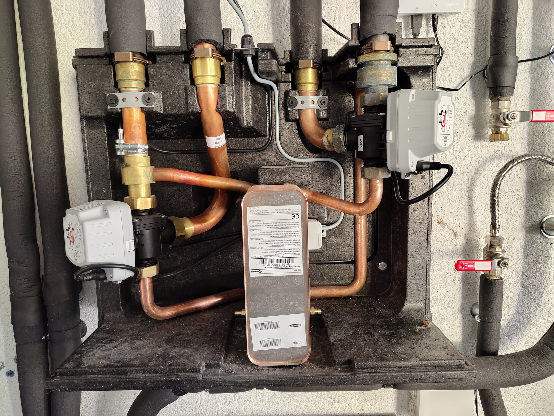
NC-Box internals and probable frost monitor. Open enclosure · straight on.Needs reviewP2 · useful detailOpen full image ↗
IMG_20260814_094538370.jpg

NC-Box interior

NC-Box internals and probable frost monitor

View
Open enclosure · straight on
Evidence
Best overview of the plate heat exchanger, motorized valve actuators and four physical upper connections in survey order NC-A through NC-D, left to right. The later labelled external QAD36 photographs supersede the earlier identification of the small silver clamp as numeric cooling-flow feedback. The clamp is now a probable physical match for the manual's internal frost-protection monitor, but its cable/terminal must be traced before that function is called confirmed.
Verify
Confirm the silver clamp's terminal and function from the serial-specific parts/wiring information; do not relabel it as the QAD36 cooling-flow sensor.
Confidence
medium
Full image
Changeover-valve actuator side label. Open enclosure · lower actuator.ConfirmedOpen full image ↗
IMG_20260814_094551387.jpg

NC-Box interior

Changeover-valve actuator side label

View
Open enclosure · lower actuator
Evidence
Label is legible enough to associate with the photographed actuator.
Confidence
high
Full image
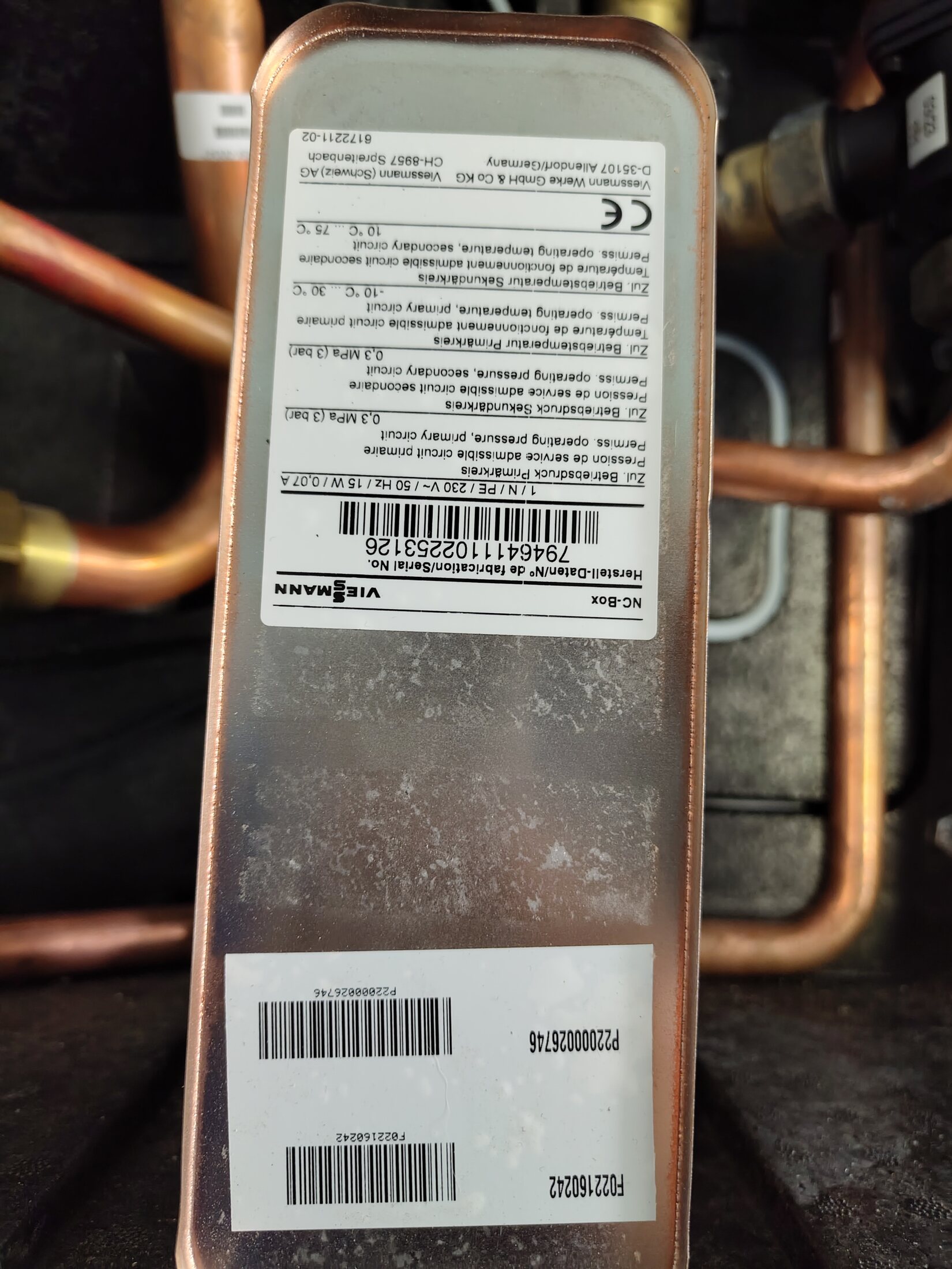
Plate heat exchanger label · second view. Open enclosure · centre.ConfirmedOpen full image ↗
IMG_20260814_094602074.jpg

NC-Box interior

Plate heat exchanger label · second view

View
Open enclosure · centre
Evidence
Second label view preserves serial/manufacturer context.
Confidence
high
Full image
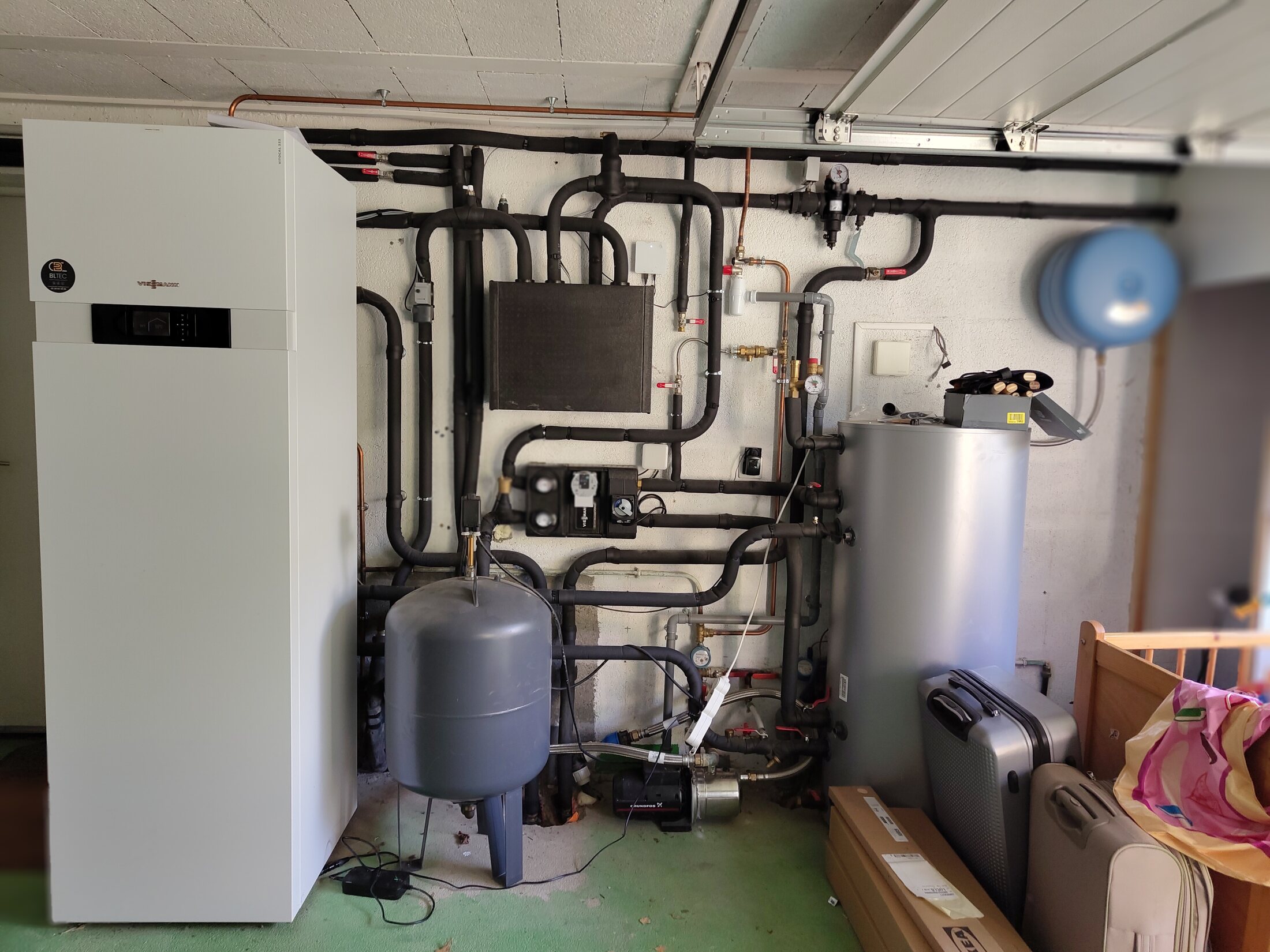
Complete plant room and confirmed borehole branch pairings. Front-facing wide view.ConfirmedP2 · useful detailOpen full image ↗
IMG_20260814_100815696.jpg

Plant-room context

Complete plant room and confirmed borehole branch pairings

View
Front-facing wide view
Evidence
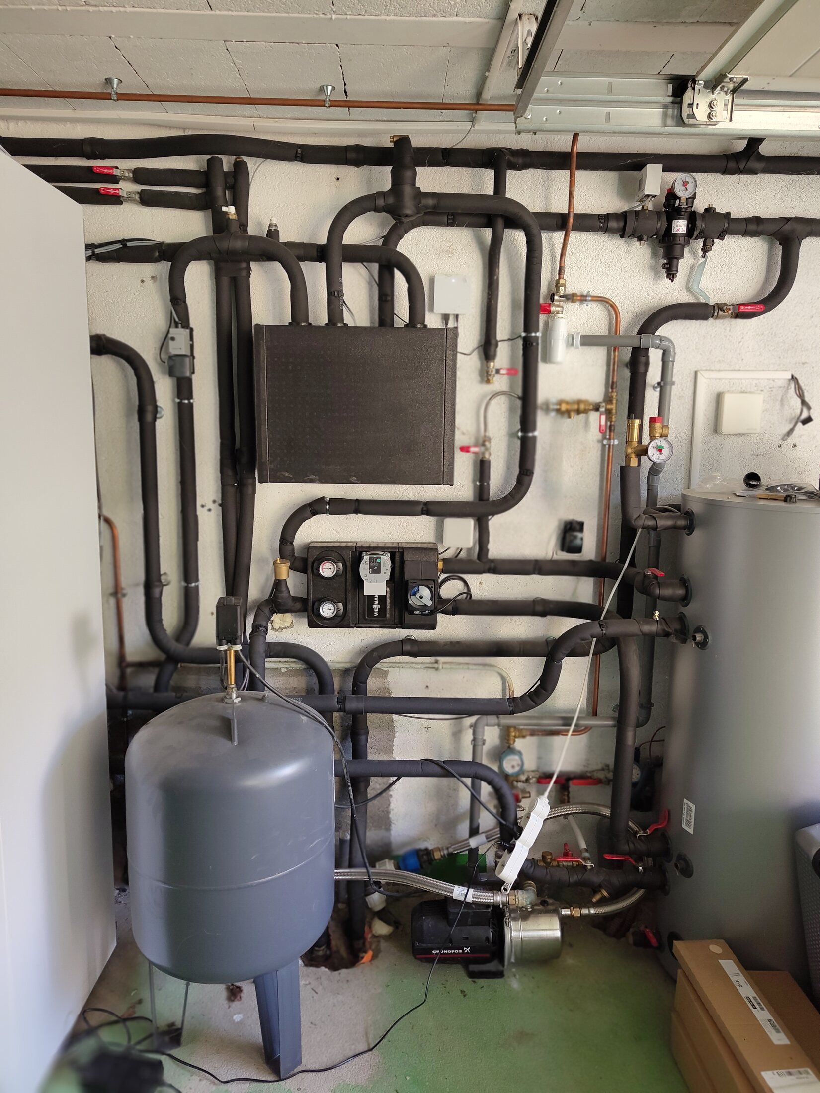
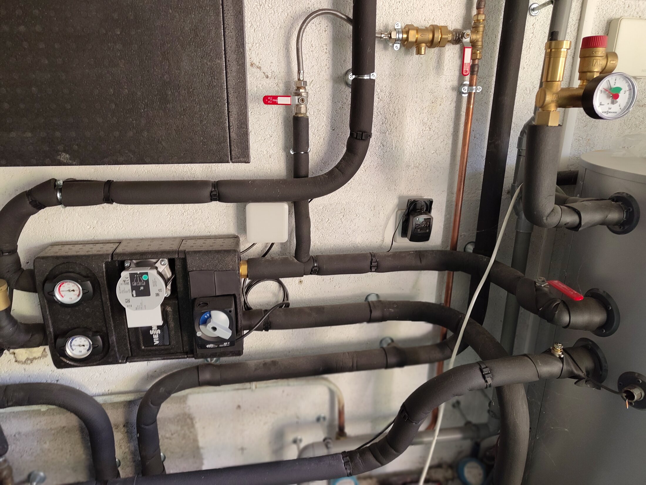
Shows the Vitocal, wall hydraulics, buffer and well-water equipment in one frame. The smaller blue pressure tank and floor-mounted Grundfos belong to the unrelated domestic well-water system and are intentionally kept out of the System schematic. Household tracing confirms NC-C ↔ BH-J1 ↔ OB-R + BH24-L and the complementary G ↔ BH-J2 ↔ OB-L + BH24-U branch behind the heat pump. No individual borehole balancing hardware is visible; one common isolation valve is visible after the branches meet. Hidden or buried balancing and the NC-Box internal direction remain unresolved.
Verify
Compare branch flows/temperatures, look for flow/return markings and confirm whether any balancing hardware is hidden or buried. Do not infer below-ground joining from the surface trace.
Confidence
high
Full image
Wall hydraulics and equipment context. Front-facing wide view.ConfirmedOpen full image ↗
IMG_20260814_100825219.jpg

Plant-room context

Wall hydraulics and equipment context

View
Front-facing wide view
Evidence
Second overview with more wall pipework visible.
Confidence
high
Full image
Secondary group, buffer and wall-pipe context. Right side of wall installation.Visible, route openP1 · topology blockerOpen full image ↗
IMG_20260814_100842560.jpg

Plant-room context

Secondary group, buffer and wall-pipe context

View
Right side of wall installation
Evidence
Connects component positions spatially; individual destinations remain partly hidden by insulation.
Verify
Use with the probe close-up to confirm the probe cable route and its height relative to BUF-3; capture any visible sensor label or wiring endpoint.
Confidence
high
Full image
Closed NC-Box and surrounding pipework. Centre wall · straight on.Visible, route openOpen full image ↗
IMG_20260814_100846712.jpg

Plant-room context

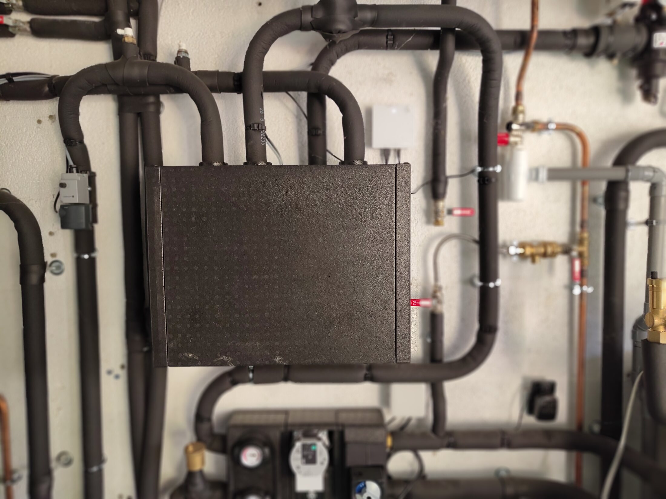
Closed NC-Box and surrounding pipework

View
Centre wall · straight on
Evidence
Useful routing context; insulation hides junctions.
Confidence
high
Full image
Borehole 1 surface pair entering the ground. Floor-level pipe entry.ConfirmedP2 · useful detailOpen full image ↗
IMG_20260814_101006571.jpg

Plant-room context

Borehole 1 surface pair entering the ground

View
Floor-level pipe entry
Evidence
Household identification confirms that the two visible pipes are Borehole 1's surface pair. OB-R is traced through BH-J1 to BH24-L; OB-L is traced through BH-J2 behind the heat pump to connector G and BH24-U. The photograph does not establish how the recalled double-U circuits join below ground.
Verify
Compare branch flows/temperatures and confirm whether any balancing hardware is hidden or buried. No individual balancing hardware is visible; one common isolation valve is visible after the branches meet.
Confidence
high
Full image
Secondary group, buffer ports and wall pipework. Right wall · wider view.Visible, route openOpen full image ↗
IMG_20260814_101014643.jpg

Plant-room context

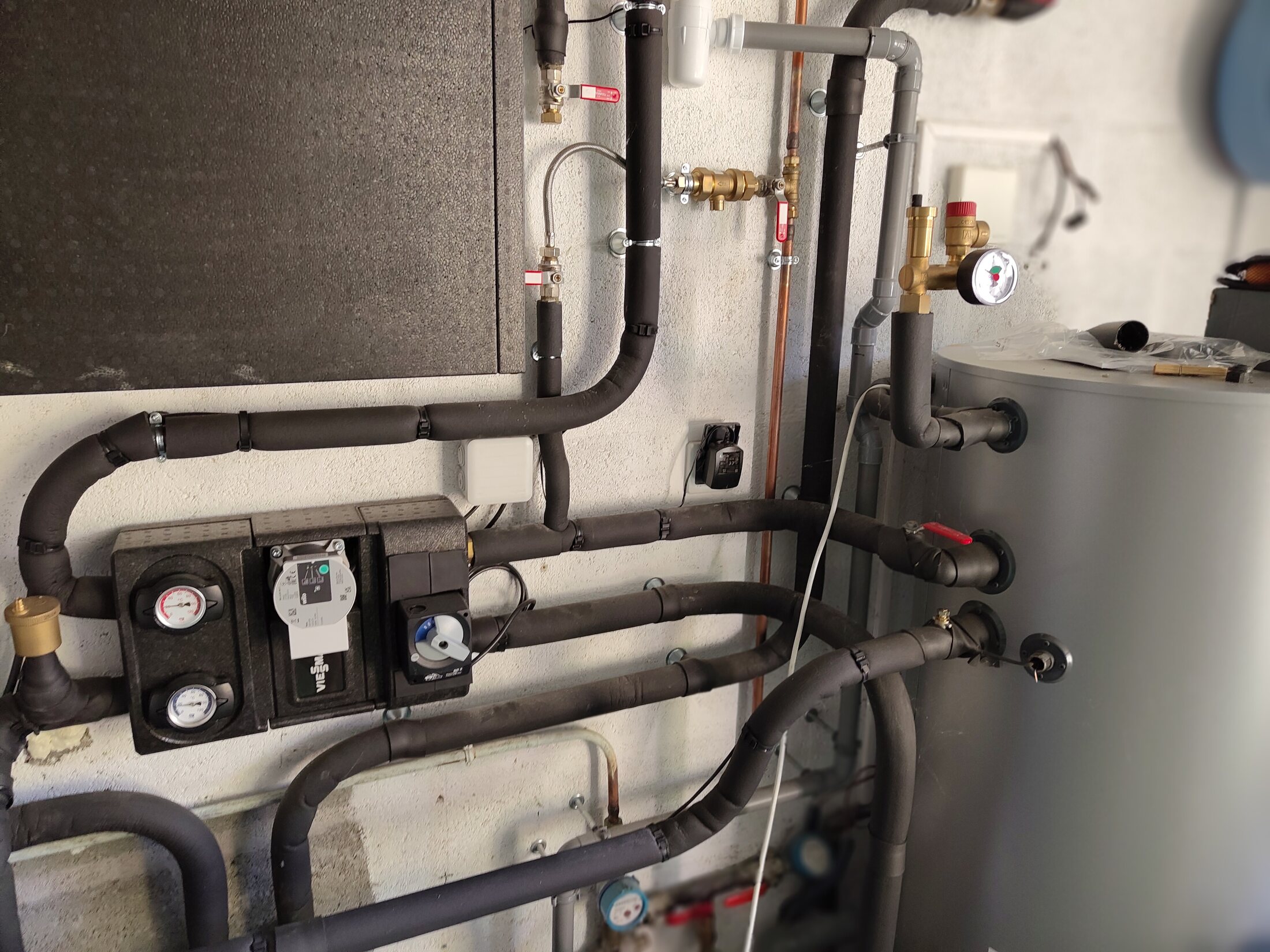
Secondary group, buffer ports and wall pipework

View
Right wall · wider view
Evidence
Good context for following visible runs toward the buffer.
Confidence
high
Full image
Copeland pressure control. High wall · left-side close-up.Needs reviewOpen full image ↗
IMG_20260814_101037687.jpg

Safety and pressure controls

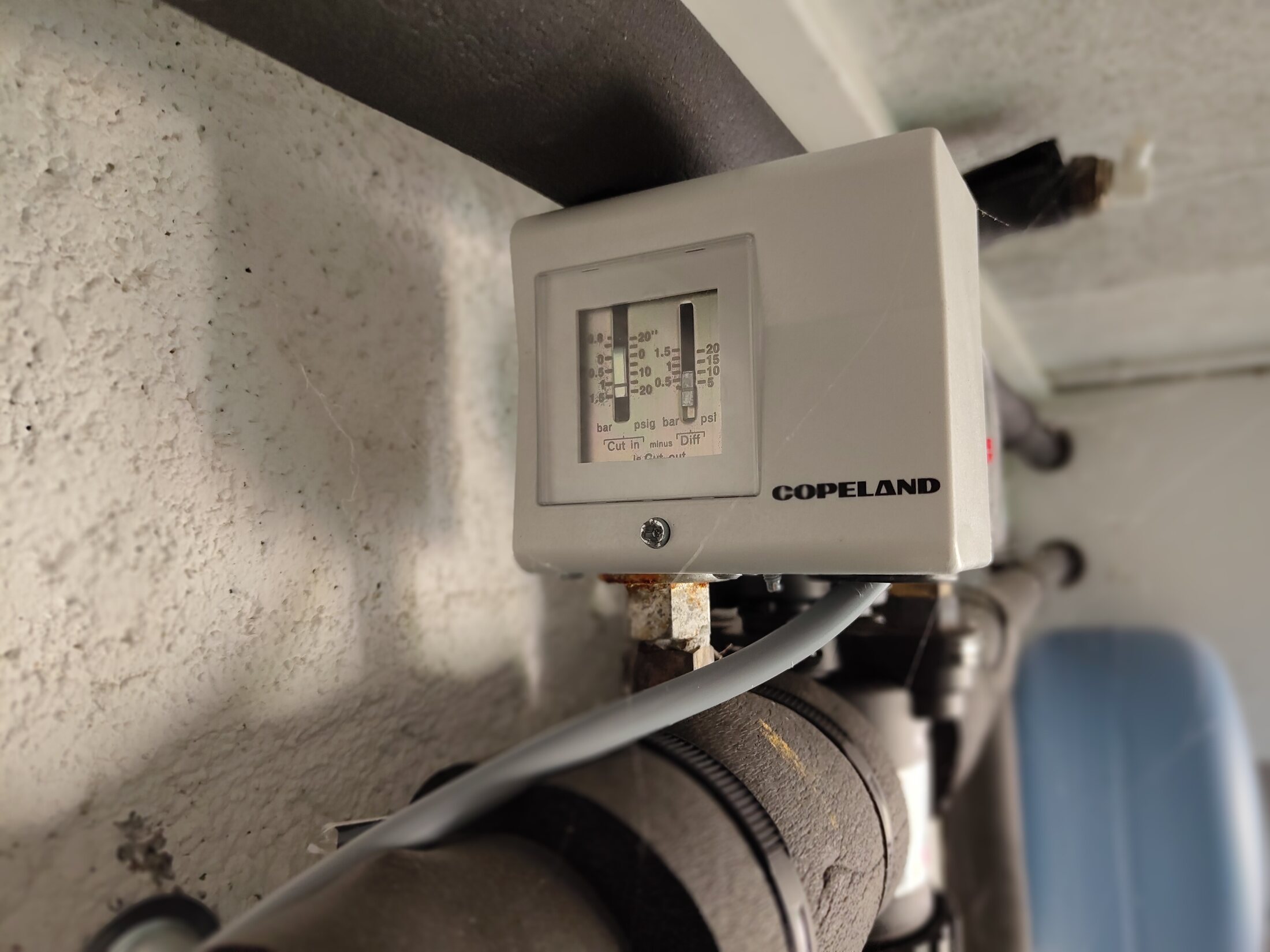
Copeland pressure control

View
High wall · left-side close-up
Evidence
Manufacturer face is visible; exact installation role/wiring still needs confirmation.
Confidence
medium
Full image
Shared pressure / safety group and gauge. High wall · front close-up.ConfirmedOpen full image ↗
IMG_20260814_101043290.jpg

Safety and pressure controls

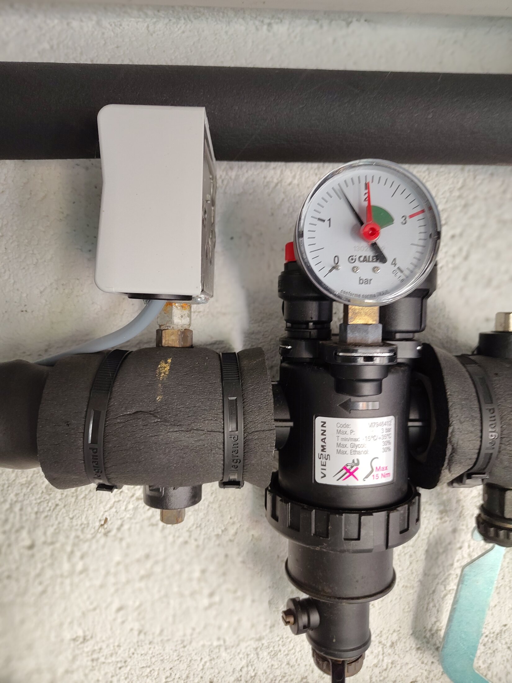
Shared pressure / safety group and gauge

View
High wall · front close-up
Evidence
Household trace places NC-Box route C through this assembly toward both boreholes.
Confidence
high
Full image
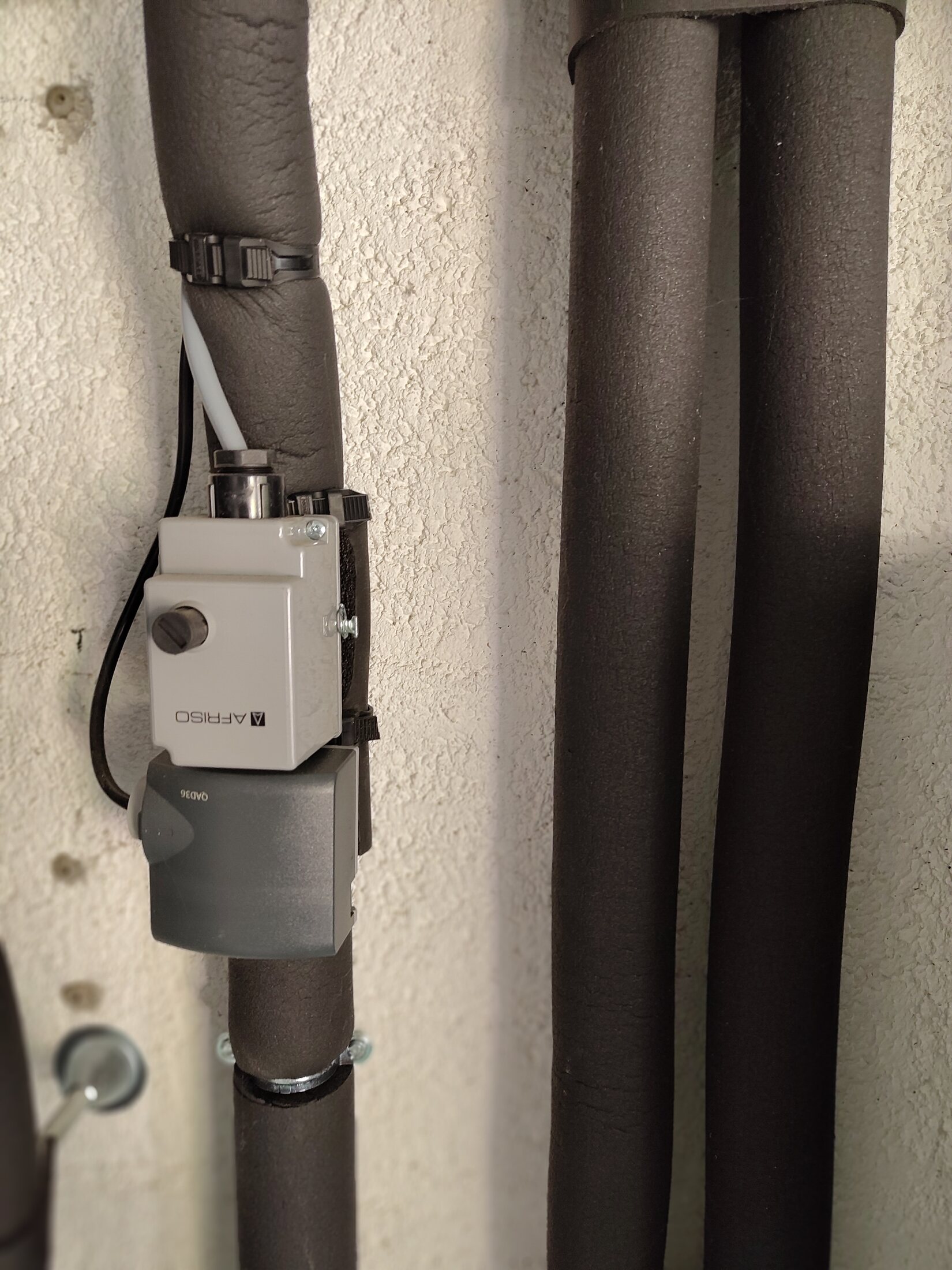
AFRISO strap-on safety aquastat. Pipe-mounted device · side.ConfirmedP2 · useful detailOpen full image ↗
IMG_20260814_101122165.jpg

Safety and pressure controls

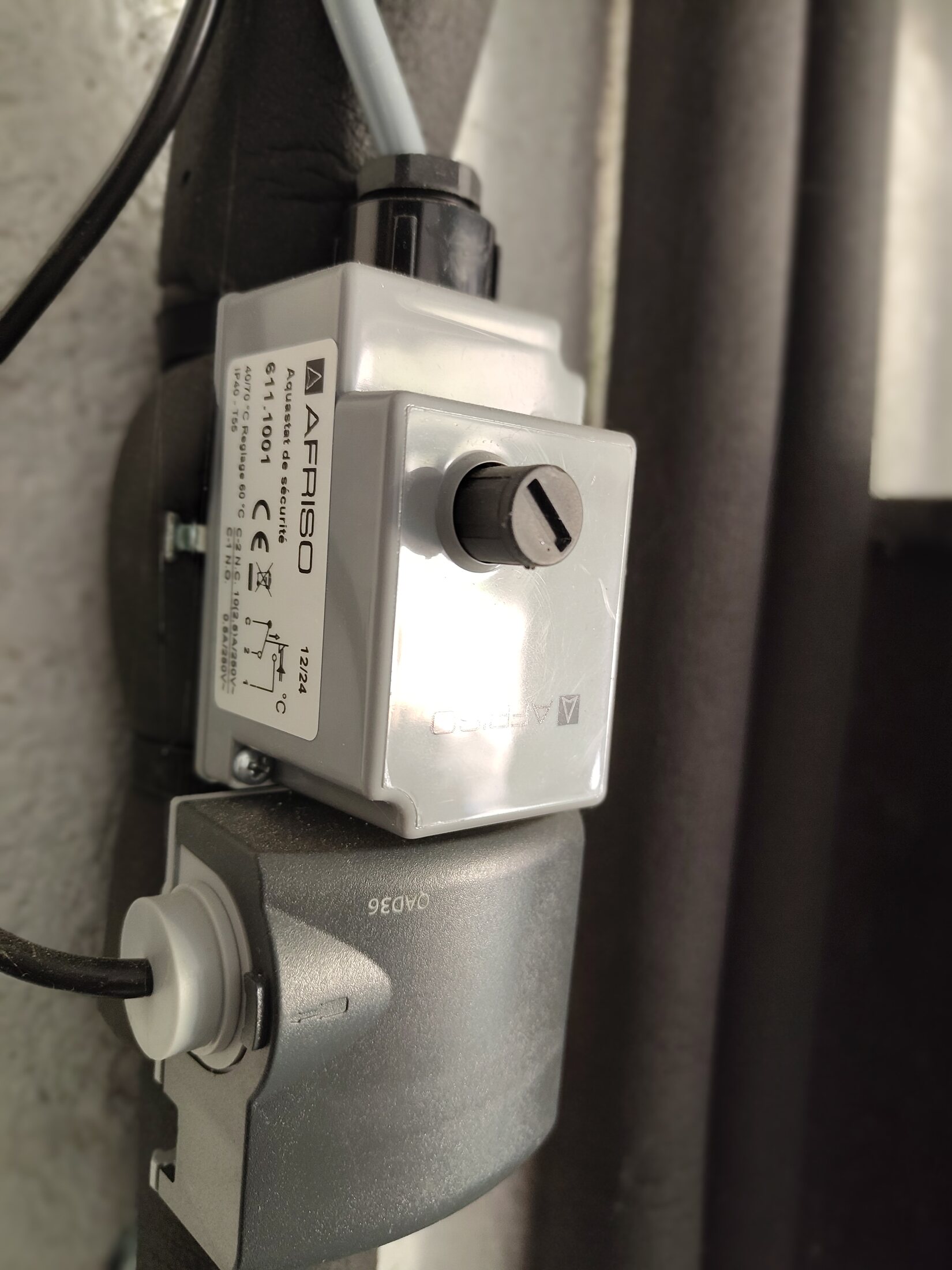
AFRISO strap-on safety aquastat

View
Pipe-mounted device · side
Evidence
Device and adjustment access are visible.
Verify
Trace the cable and switched circuit to confirm the aquastat's installed safety association.
Confidence
high
Full image
AFRISO aquastat in pipe context. Pipe-mounted device · full view.ConfirmedP2 · useful detailOpen full image ↗
IMG_20260814_101126736.jpg

Safety and pressure controls

AFRISO aquastat in pipe context

View
Pipe-mounted device · full view
Evidence
Household trace places route A past this device toward the lower-floor manifold.
Verify
Confirm the strap-on sensing point, cable destination and whether it interrupts the floor circuit.
Confidence
high
Full image
AFRISO 611.1001 label. Pipe-mounted device · label close-up.ConfirmedP2 · useful detailOpen full image ↗
IMG_20260814_101141249.jpg

Safety and pressure controls

AFRISO 611.1001 label

View
Pipe-mounted device · label close-up
Evidence
Model and 40–70 °C range are readable.
Verify
Record the actual dial setting and reconcile it with the traced cable/function.
Confidence
high
Full image
AFRISO aquastat and separate Siemens QAD36 sensor. NC-A pipe · device context.ConfirmedOpen full image ↗
safety-controls/2026-08-17/IMG_20260817_134924941.jpg

Safety and pressure controls

AFRISO aquastat and separate Siemens QAD36 sensor

View
NC-A pipe · device context
Evidence
Shows both strapped devices in their installed order on the confirmed NC-A emitter supply. The grey QAD36 is physically separate from the white AFRISO high-limit thermostat.
Confidence
high
Full image
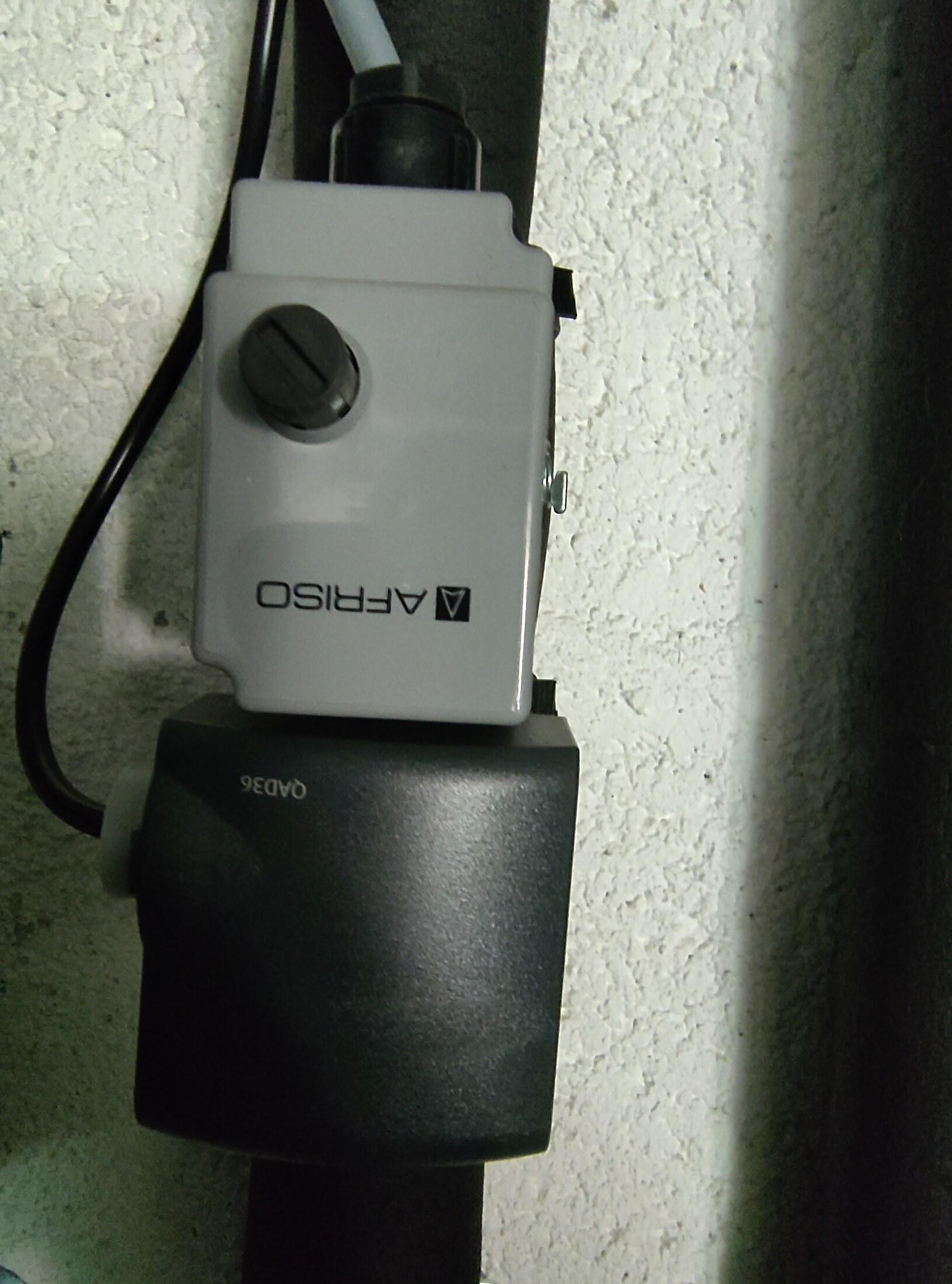
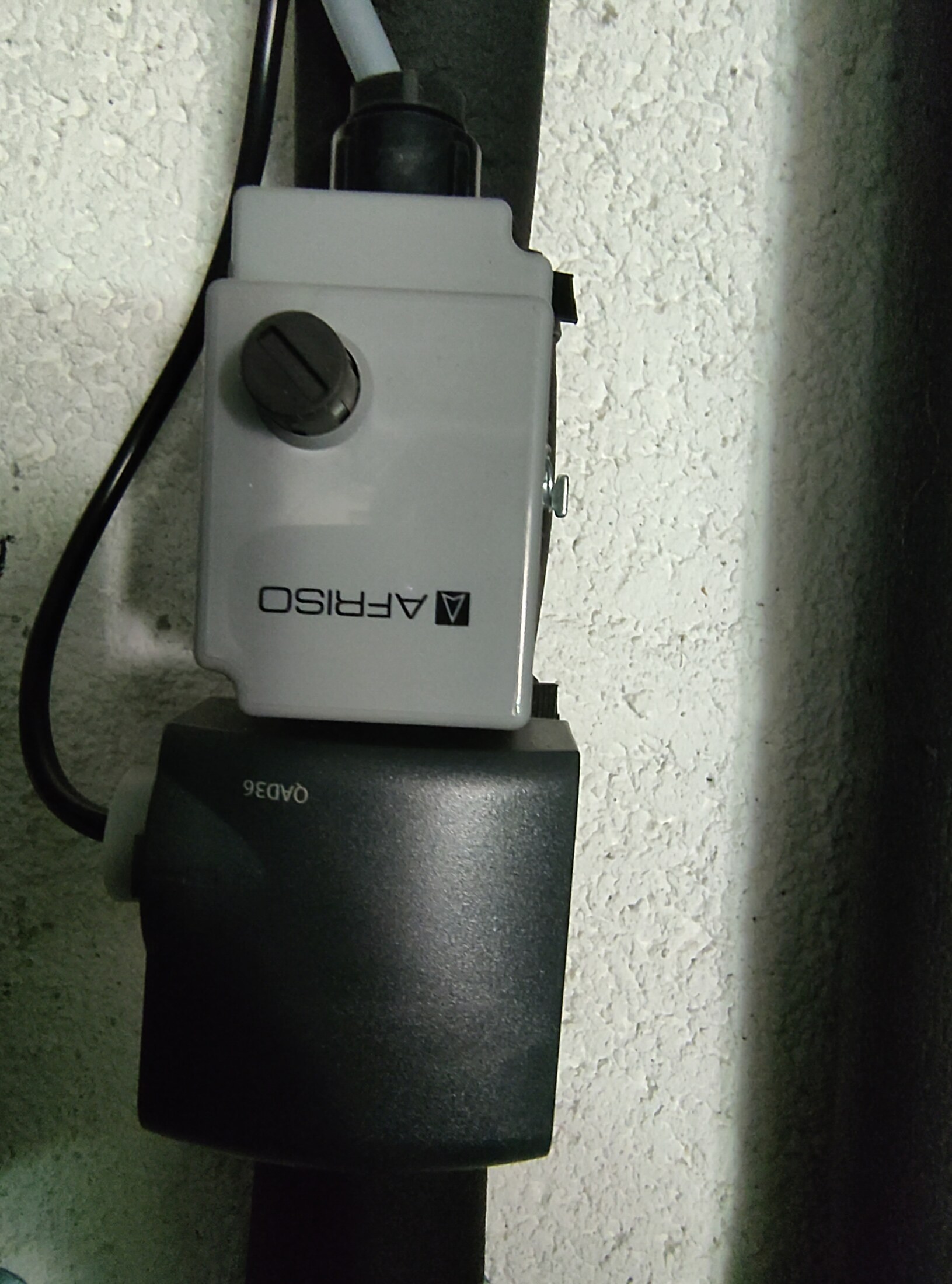
Siemens QAD36 cooling-flow temperature sensor. NC-A pipe · label close-up.ConfirmedP2 · useful detailOpen full image ↗
safety-controls/2026-08-17/IMG_20260817_134925399.jpg

Safety and pressure controls

Siemens QAD36 cooling-flow temperature sensor

View
NC-A pipe · label close-up
Evidence
The `QAD36` family marking is directly readable. Siemens documents this family as an NTC 10 kOhm strap-on temperature sensor; its NC-A location, enabled controller input and simultaneous local 18 °C cooling-flow diagnostic establish the installed role. It is not a humidistat.
Verify
The /101 or /201 cable-length suffix is not visible; confirm only if exact replacement ordering is needed.
Confidence
high
Full image
No separate contact humidistat visible in surveyed pipework. Above NC-Box · accessible pipe survey.Needs reviewP1 · topology blockerOpen full image ↗
safety-controls/2026-08-17/IMG_20260817_134930702.jpg

Safety and pressure controls

No separate contact humidistat visible in surveyed pipework

View
Above NC-Box · accessible pipe survey
Evidence
Records the insulated pipes directly above the NC-Box after the household surveyed the accessible route. No ribbed contact humidistat matching the supplied manual drawing is visible; absence cannot be proved because a contact may be hidden or relocated.
Verify
Installer should trace and trip-test the F11/NC-Box humidity-safety circuit, rule out a bridge, and verify vapour-tight insulation.
Confidence
medium
Full image
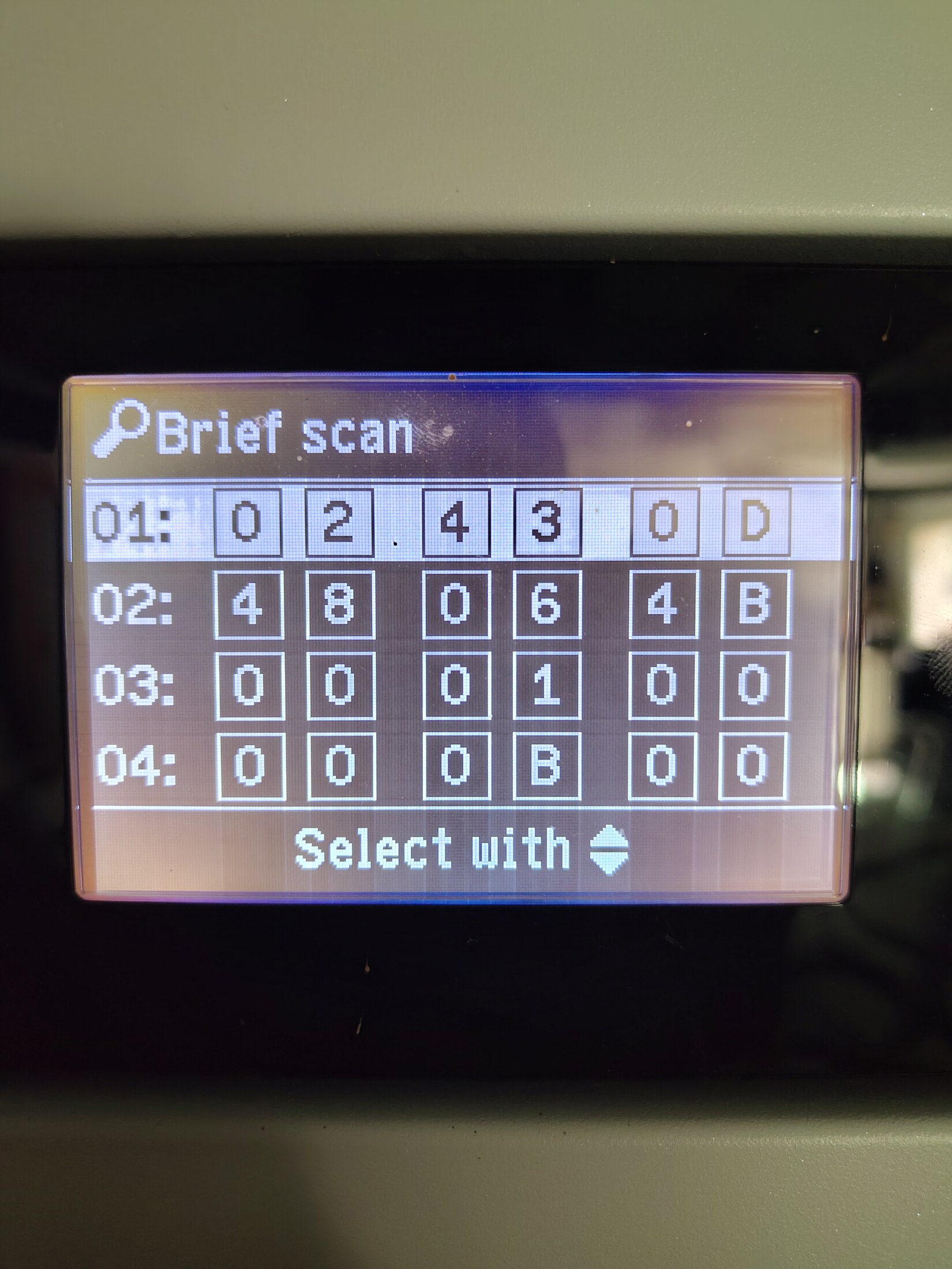
Controller, coding-card and refrigerant-controller identifiers. WO1C Brief scan · rows 01–04.ConfirmedOpen full image ↗
controller-diagnostics/2026-08-17/IMG_20260817_133802884.jpg

Heat-pump controller · 17 August

Controller, coding-card and refrigerant-controller identifiers

View
WO1C Brief scan · rows 01–04
Evidence
Direct read-only Brief scan capture: row 01 `0 2 4 3 0 D`, row 02 `4 8 0 6 4 B`, row 03 `0 0 0 1 0 0`, and row 04 `0 0 0 B 0 0`. The manual's field grouping maps row 04 to refrigerant-controller hardware 00/software 0B and zero in both mixer-extension software fields.
Confidence
high
Full image
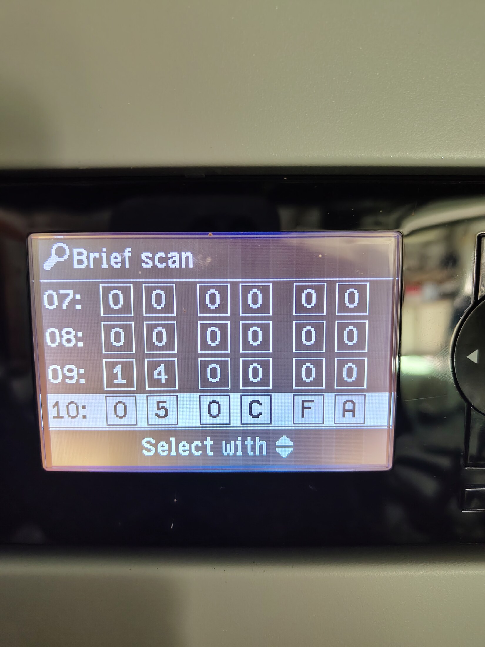
Remote-control and controller software identifiers. WO1C Brief scan · rows 07–10.ConfirmedOpen full image ↗
controller-diagnostics/2026-08-17/IMG_20260817_133827315.jpg

Heat-pump controller · 17 August

Remote-control and controller software identifiers

View
WO1C Brief scan · rows 07–10
Evidence
Direct capture includes row 09 `14 00 00` and row 10 `05 0C FA` in the documented field grouping.
Confidence
high
Full image
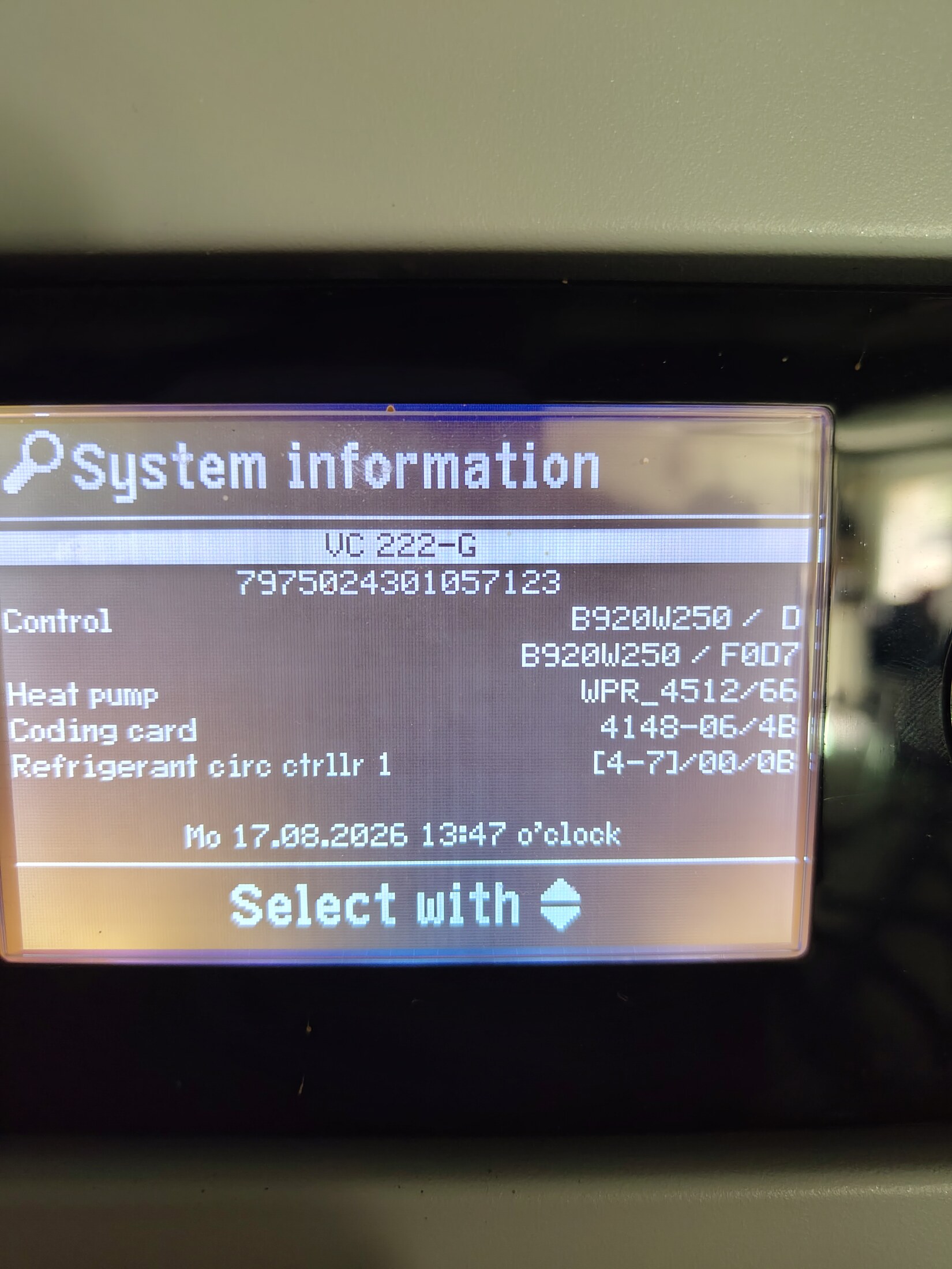
Installed controller and coding-card identity. WO1C System information.ConfirmedOpen full image ↗
controller-diagnostics/2026-08-17/IMG_20260817_133848862.jpg

Heat-pump controller · 17 August

Installed controller and coding-card identity

View
WO1C System information
Evidence
Direct display of VC 222-G, serial 7975024301057123, WPR_4512/66 and coding card 4148-06/4B.
Confidence
high
Full image
Synchronized outside and primary/secondary temperatures. Temperature sensors · page 1.ConfirmedOpen full image ↗
controller-diagnostics/2026-08-17/IMG_20260817_133915788.jpg

Heat-pump controller · 17 August

Synchronized outside and primary/secondary temperatures

View
Temperature sensors · page 1
Evidence
Direct capture during Natural Cooling: outside 31 °C, primary flow/return 17/18 °C and secondary flow 31 °C.
Confidence
high
Full image
Synchronized actual cooling-flow temperature. Temperature sensors · page 3.ConfirmedOpen full image ↗
controller-diagnostics/2026-08-17/IMG_20260817_133929478.jpg

Heat-pump controller · 17 August

Synchronized actual cooling-flow temperature

View
Temperature sensors · page 3
Evidence
Direct capture reports heating-circuit room 23 °C and `Flow temp. cooling 18 °C`, matching the QAD36 sensing point rather than the separate cloud target.
Confidence
high
Full image
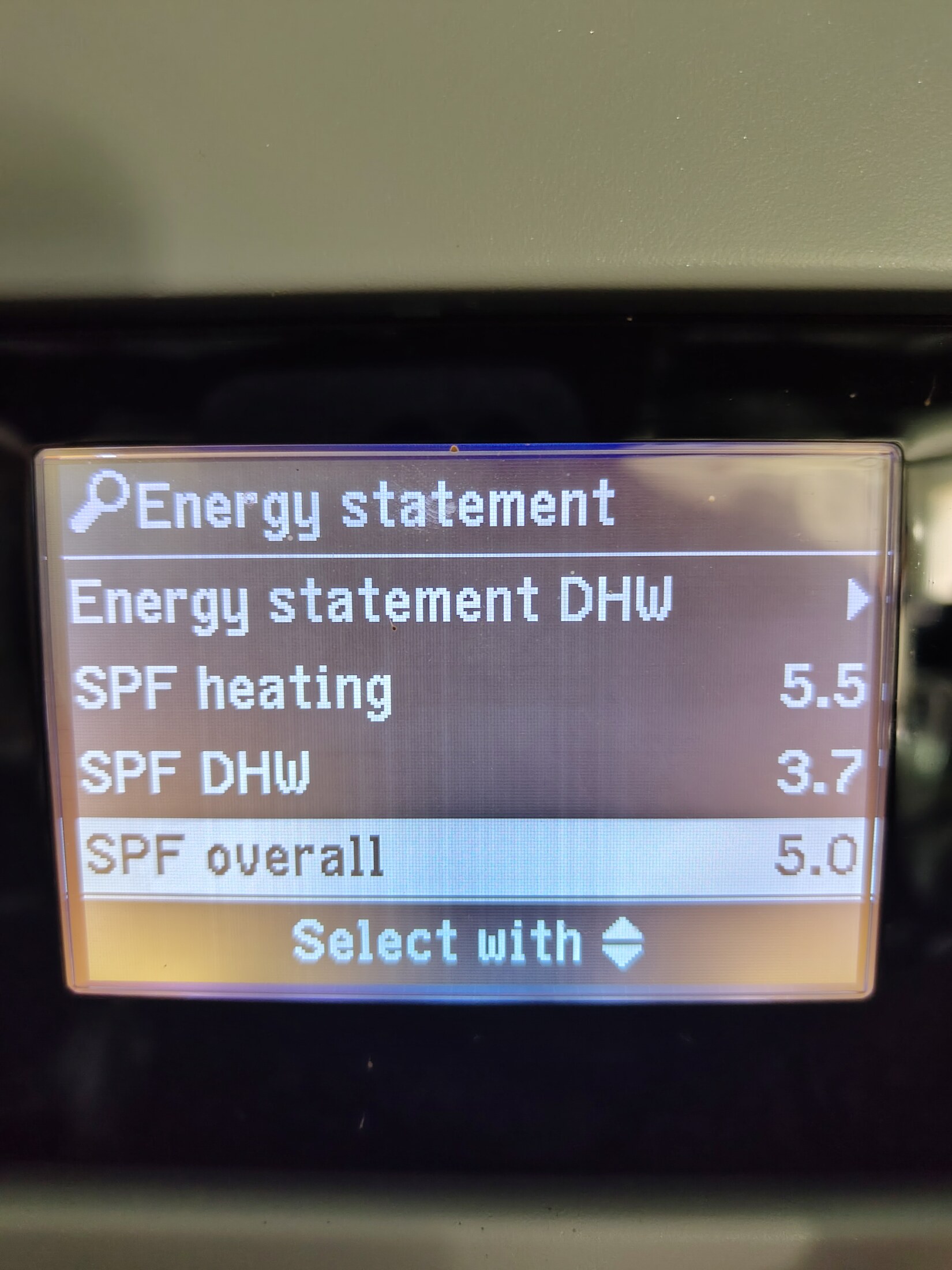
Controller Seasonal Performance Factor. Energy statement.ConfirmedOpen full image ↗
controller-diagnostics/2026-08-17/IMG_20260817_134018045.jpg

Heat-pump controller · 17 August

Controller Seasonal Performance Factor

View
Energy statement
Evidence
Direct display reports SPF heating 5.5, DHW 3.7 and overall 5.0. These controller figures retain their own accounting boundary and are future comparison values, not validation of the provisional Home Assistant estimates.
Confidence
high
Full image
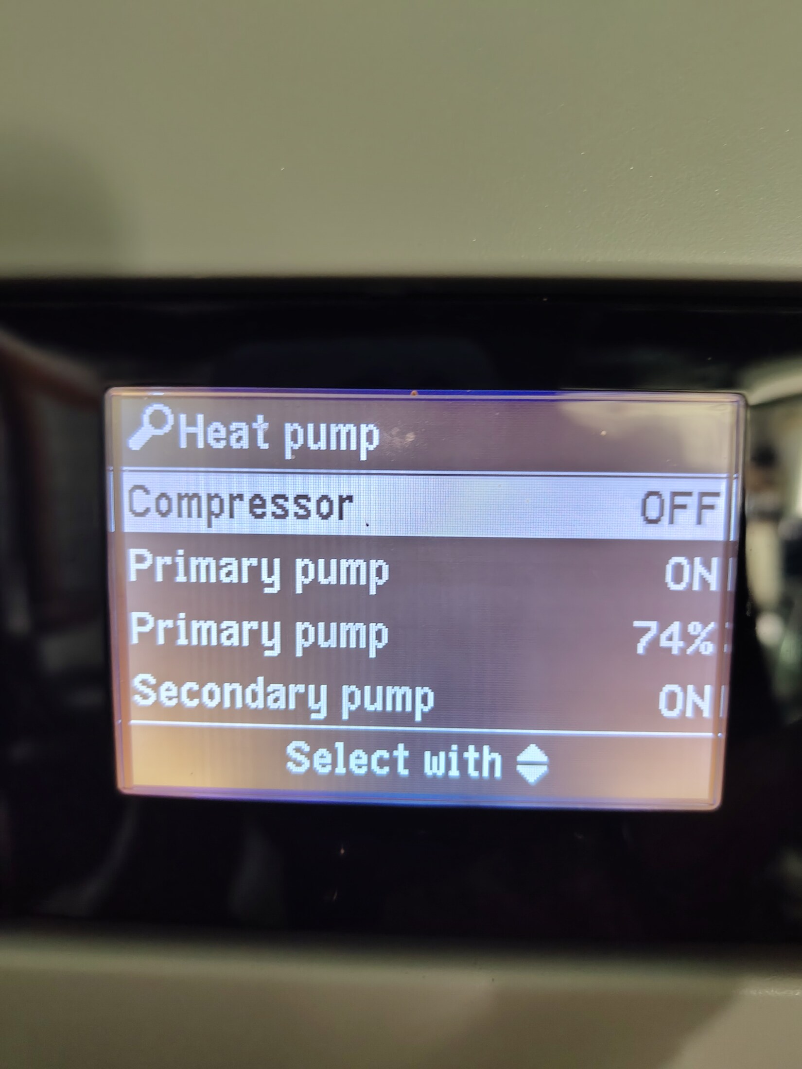
Passive-cooling equipment state. Heat-pump status · page 1.ConfirmedOpen full image ↗
controller-diagnostics/2026-08-17/IMG_20260817_134105583.jpg

Heat-pump controller · 17 August

Passive-cooling equipment state

View
Heat-pump status · page 1
Evidence
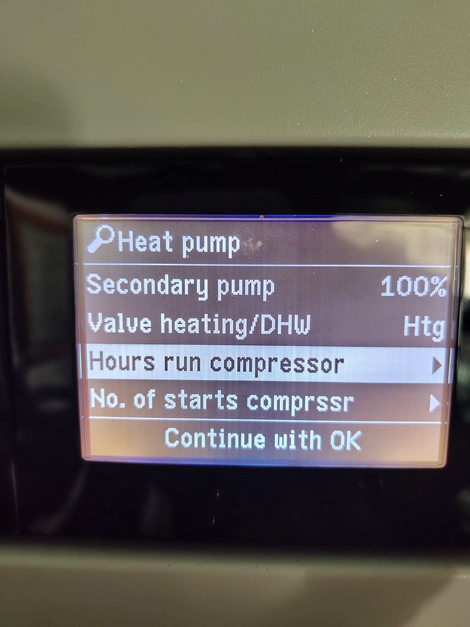
Direct capture shows compressor off and both primary and secondary pumps on.
Confidence
high
Full image
Synchronized pump commands. Heat-pump status · page 2.ConfirmedOpen full image ↗
controller-diagnostics/2026-08-17/IMG_20260817_134109635.jpg

Heat-pump controller · 17 August

Synchronized pump commands

View
Heat-pump status · page 2
Evidence
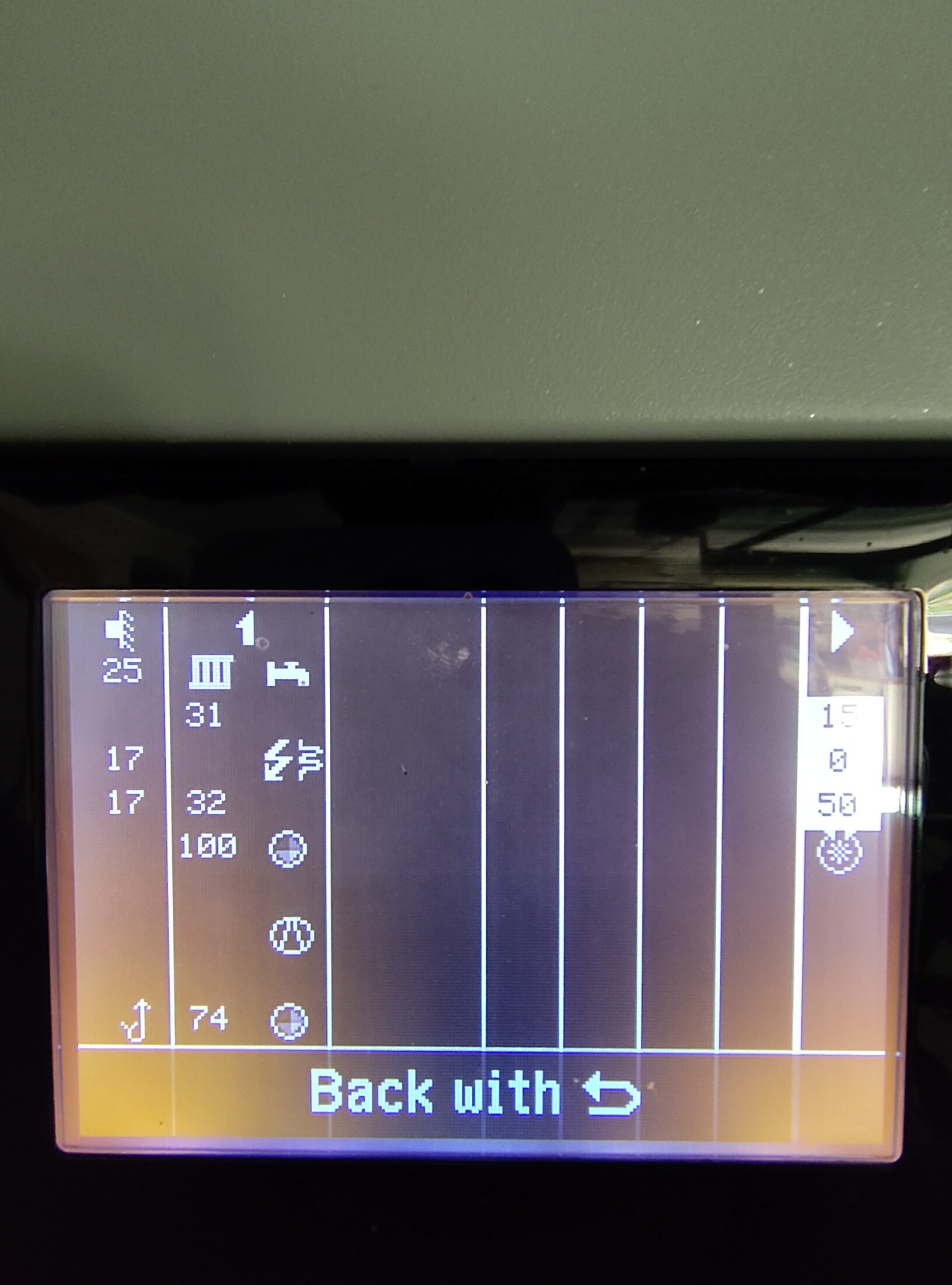
Direct capture shows primary pump 74%, secondary pump 100% and the heating/DHW valve in heating position during Natural Cooling.
Confidence
high
Full image
Synchronized hydraulic overview. System overview.ConfirmedOpen full image ↗
controller-diagnostics/2026-08-17/IMG_20260817_134250642.jpg

Heat-pump controller · 17 August

Synchronized hydraulic overview

View
System overview
Evidence
Direct controller overview captured in the same passive-cooling sequence; the second photographed overview was the same side rather than an additional hidden view.
Confidence
high
Full image
Backup-heater stage 1 cumulative runtime. Information · heat pump.ConfirmedOpen full image ↗
controller-diagnostics/2026-08-17/IMG_20260817_134808062.jpg

Heat-pump controller · 17 August

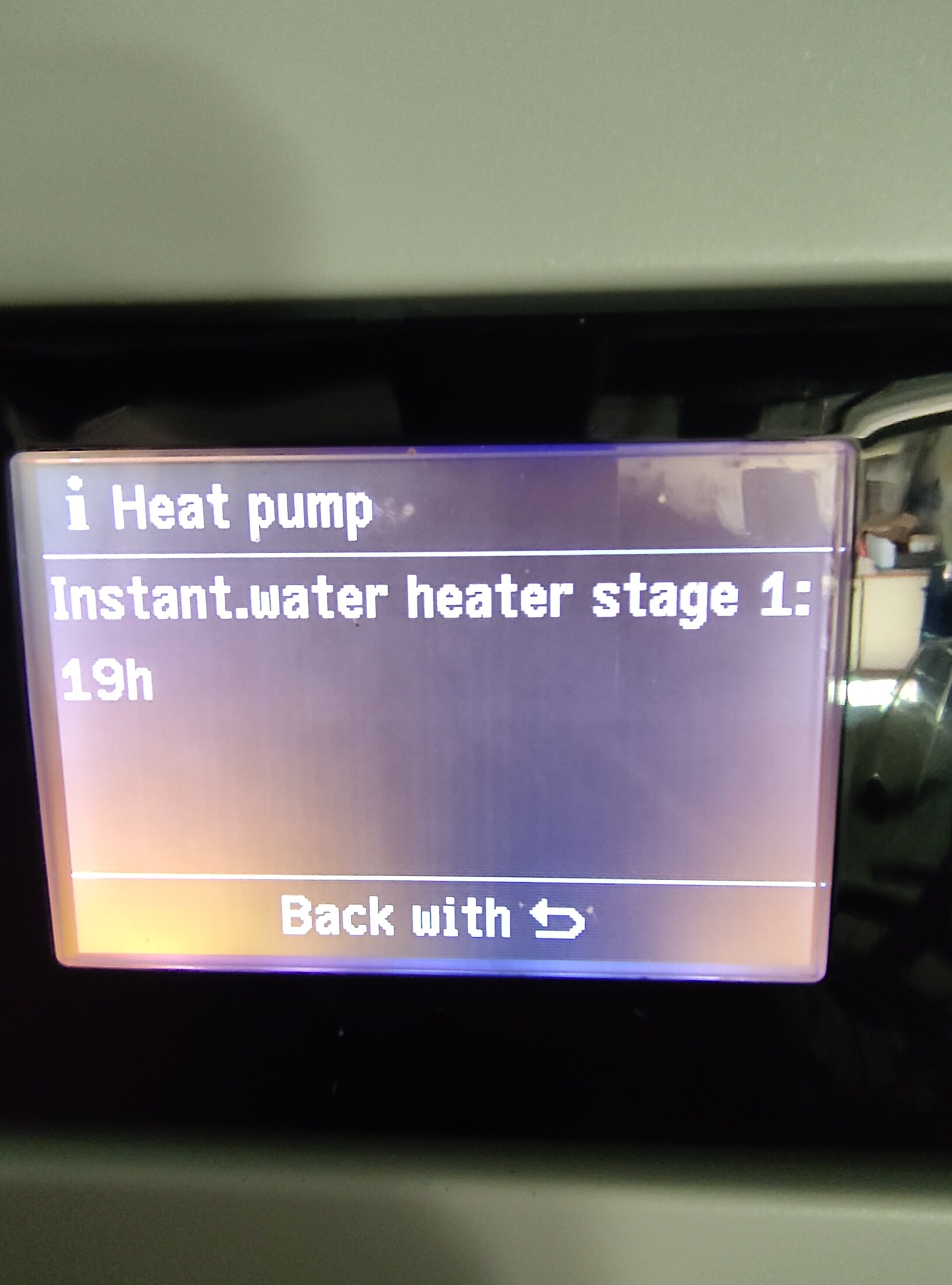
Backup-heater stage 1 cumulative runtime

View
Information · heat pump
Evidence
LCD reports 19 h, agreeing with the cloud counter's more precise 19 h 27 min 23 s.
Confidence
high
Full image
Backup-heater stage 2 cumulative runtime. Information · heat pump.ConfirmedOpen full image ↗
controller-diagnostics/2026-08-17/IMG_20260817_134812938.jpg

Heat-pump controller · 17 August

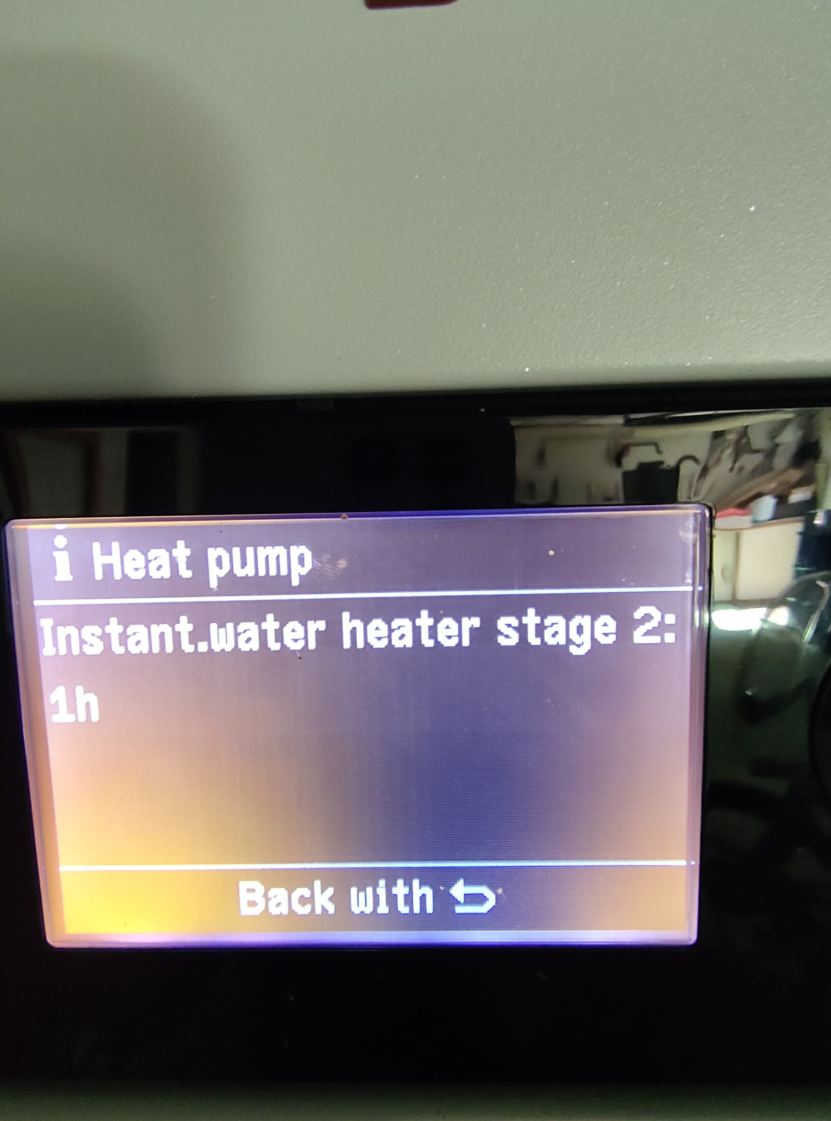
Backup-heater stage 2 cumulative runtime

View
Information · heat pump
Evidence
LCD reports 1 h, agreeing with the cloud counter's more precise 1 h 9 min 16 s and confirming historical stage-2 use.
Confidence
high
Full image
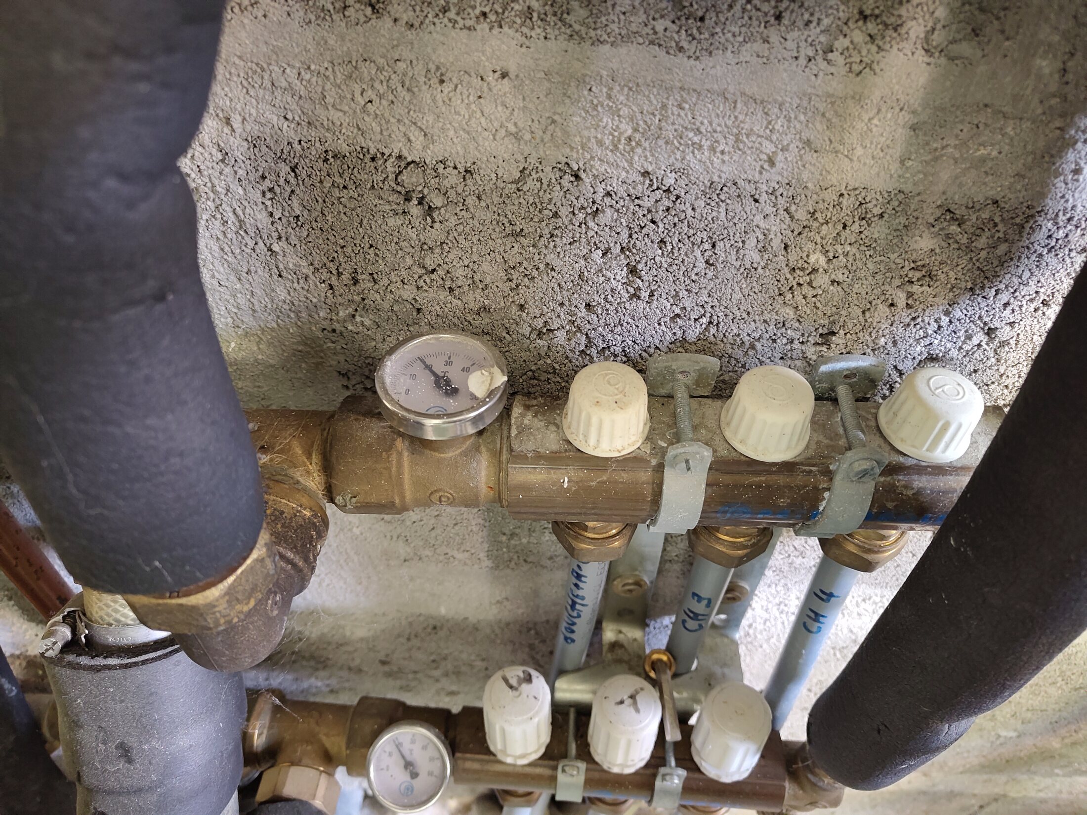
Lower-floor manifold headers. Lower-floor manifold · overhead.ConfirmedOpen full image ↗
IMG_20260814_111050557.jpg

Buffer and lower manifold

Lower-floor manifold headers

View
Lower-floor manifold · overhead
Evidence
Visible file content is the manifold. Household trace places route A at its upper header via AFRISO.
Confidence
high
Full image
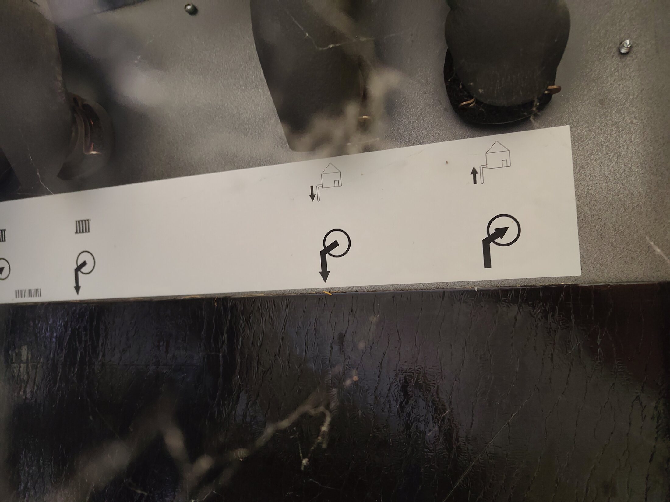
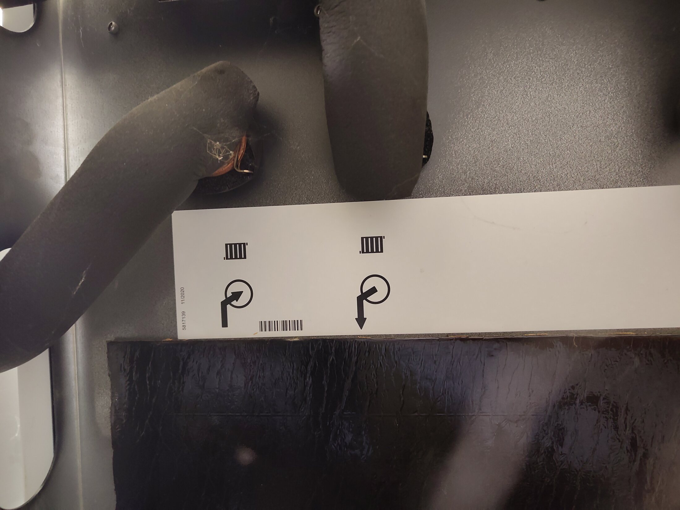
Rear heat-pump ports · right-hand half. Rear-right half of paired panorama.ConfirmedOpen full image ↗
IMG_20260814_111432978.jpg

Heat-pump rear ports

Rear heat-pump ports · right-hand half

View
Rear-right half of paired panorama
Evidence
Together with 111438420 this spans all four lower rear ports and their manufacturer pictograms. Reversing the rear orientation and checking traced destinations confirms installed F, G, E and D in front-facing left-to-right order.
Confidence
high
Full image
Rear heat-pump ports · left-hand half. Rear-left half of paired panorama.ConfirmedOpen full image ↗
IMG_20260814_111438420.jpg

Heat-pump rear ports

Rear heat-pump ports · left-hand half

View
Rear-left half of paired panorama
Evidence
Together with 111432978 this spans all four lower rear ports and their manufacturer pictograms. Reversing the rear orientation and checking traced destinations confirms installed F, G, E and D in front-facing left-to-right order.
Confidence
high
Full image
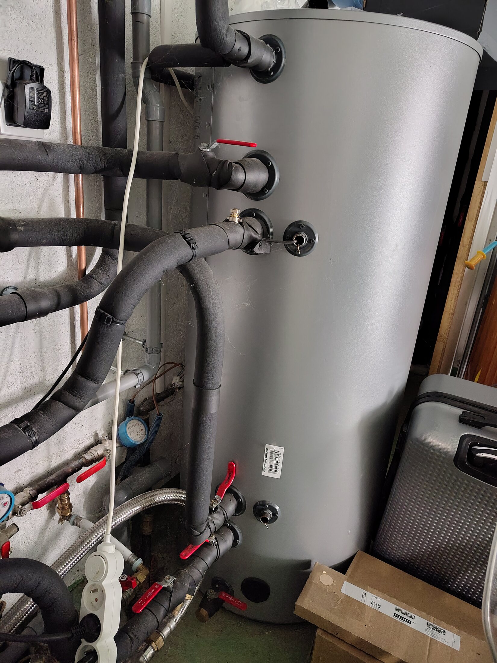
Buffer tank side-port context · partial view. Buffer · right-side partial view.Visible, route openOpen full image ↗
IMG_20260814_113200926.jpg

Buffer and lower manifold

Buffer tank side-port context · partial view

View
Buffer · right-side partial view
Evidence
Large grey tank is household-confirmed as the heat-pump buffer. This angle does not show the complete five-port set; the clearest count and traced destinations come from buffer-details/IMG_20260814_113151522.jpg and the household survey.
Confidence
high
Full image
Connector E endpoint of direct BUF-3 route. Rear heat-pump close-up.ConfirmedOpen full image ↗
IMG_20260814_113445741.jpg

Heat-pump rear ports

Connector E endpoint of direct BUF-3 route

View
Rear heat-pump close-up
Evidence
The connection and return pictogram are visible. Household physical recheck confirms BUF-3 reaches E directly and does not touch the source pressure/safety group; paired rear evidence identifies E as heating-water return.
Confidence
high
Full image
Connector D endpoint of BUF-5 route. Rear heat-pump close-up.ConfirmedOpen full image ↗
IMG_20260814_113635734.jpg

Heat-pump rear ports

Connector D endpoint of BUF-5 route

View
Rear heat-pump close-up
Evidence
The connection and flow pictogram are visible. Household physical recheck confirms BUF-5 reaches rightmost front-facing D; paired rear evidence identifies D as heating-water flow.
Confidence
high
Full image
Five connected buffer ports and sensor-pocket context. Buffer · full connected side.ConfirmedP2 · useful detailOpen full image ↗
buffer-details/IMG_20260814_113151522.jpg

Buffer tank details

Five connected buffer ports and sensor-pocket context

View
Buffer · full connected side
Evidence
Best single view of the five connected side ports from BUF-1 to BUF-5. Household physical recheck confirms all five mapped routes, including BUF-3 as a direct route to connector E with no source pressure/safety-group connection. The narrow wired probe pocket beside the BUF-3-height connection is also visible; exact manufacturer nozzle functions remain unresolved.
Verify
Capture the complete tank nameplate and expansion-vessel service/pre-charge details; retain the confirmed five route endpoints and keep BUF-3 separate from SG-1.
Confidence
high
Full image
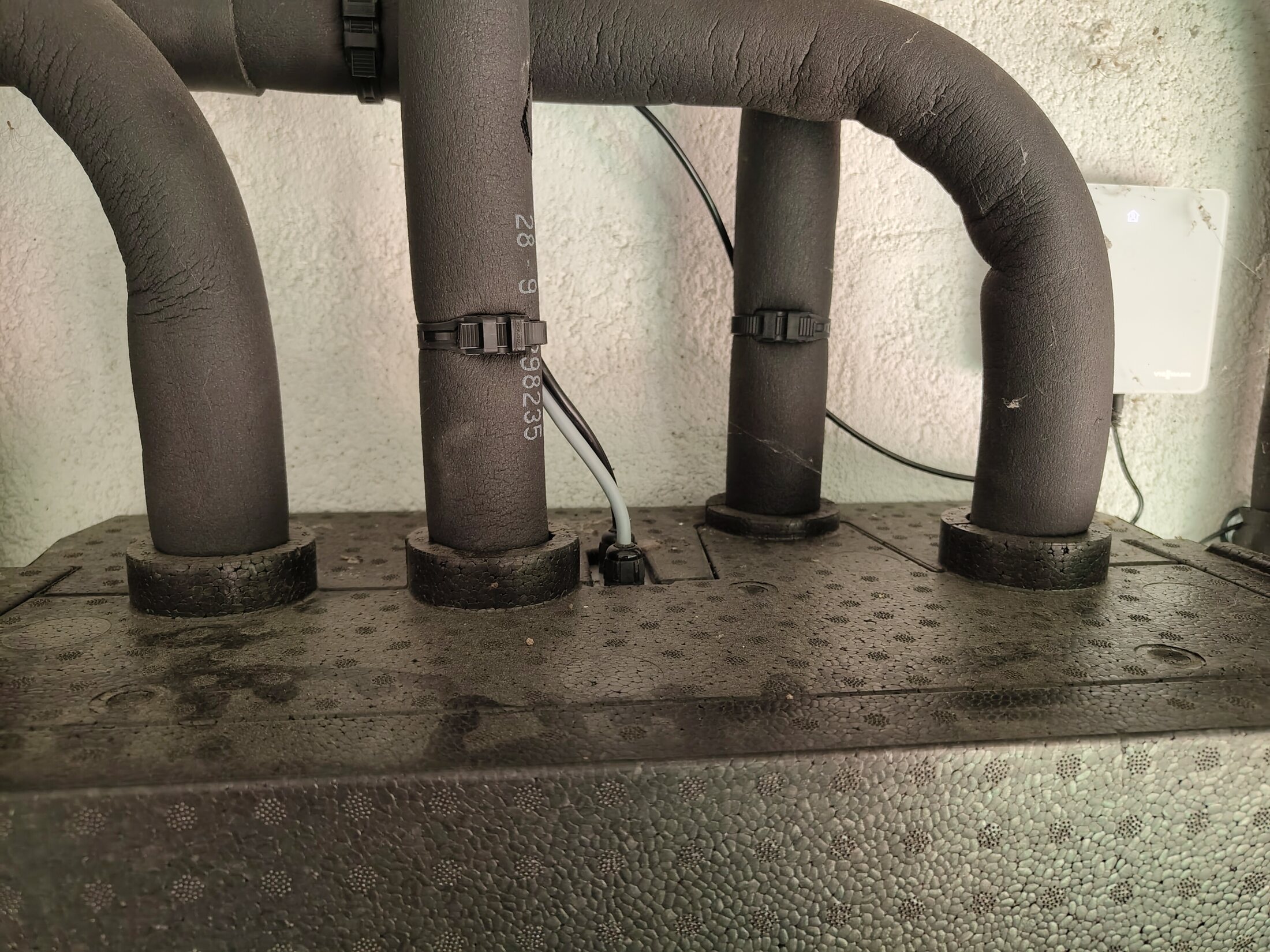
Four upper pipe runs at the secondary pump / mixer group. Top of insulated group · straight on.Visible, route openOpen full image ↗
secondary-pump-group/IMG_20260814_120404480_HDR.jpg

Secondary pump / mixer group

Four upper pipe runs at the secondary pump / mixer group

View
Top of insulated group · straight on
Evidence
Direct context view of the insulated pipe runs and cable entry. Destinations are only those supported by separate household tracing.
Confidence
high
Full image
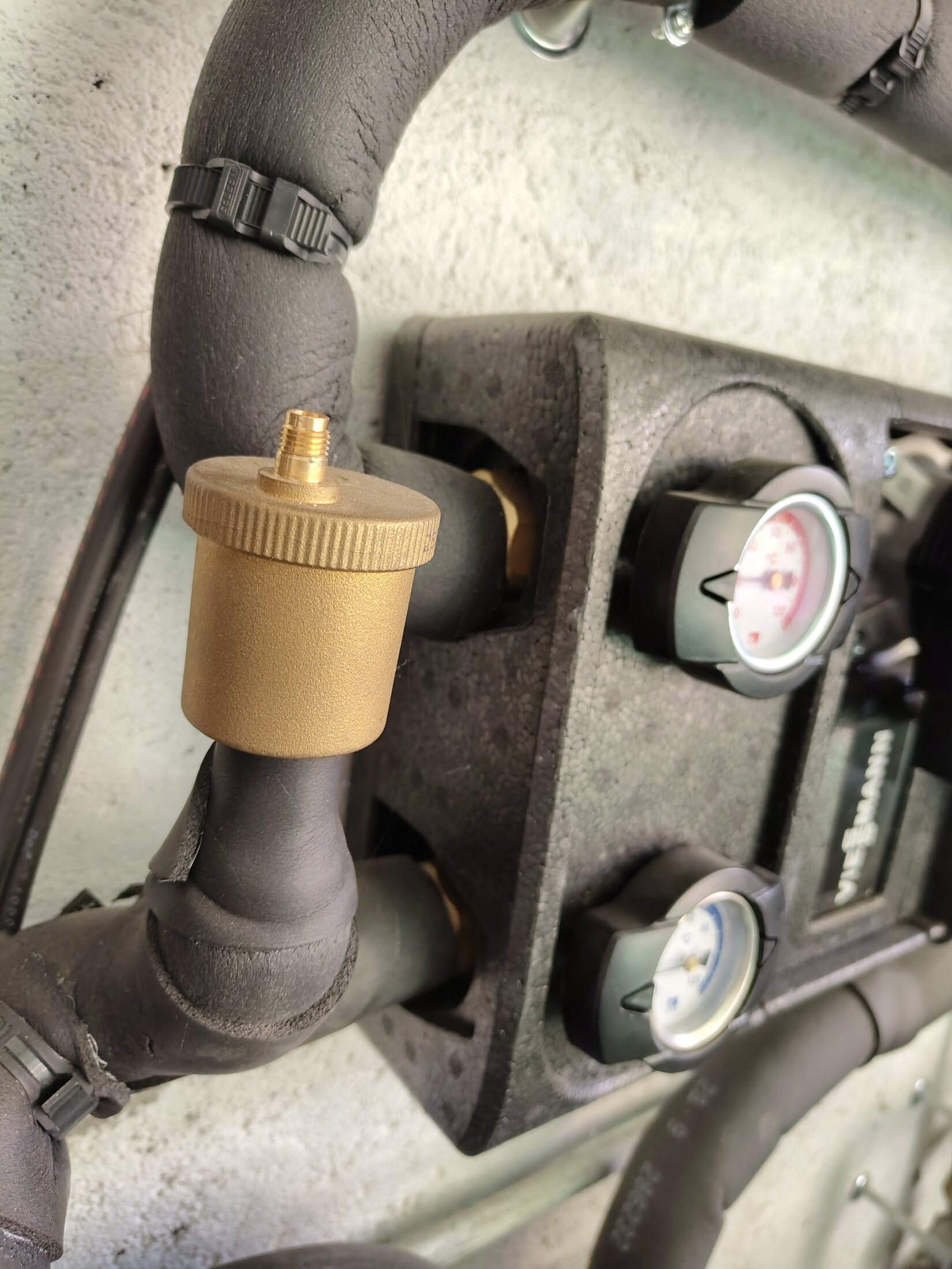
Brass automatic air vent beside secondary group. Left piping · close-up.ConfirmedOpen full image ↗
secondary-pump-group/IMG_20260814_120613463_HDR.jpg

Secondary pump / mixer group

Brass automatic air vent beside secondary group

View
Left piping · close-up
Evidence
Direct close-up identifies the component shape and placement; pipe destination is not inferred.
Confidence
high
Full image
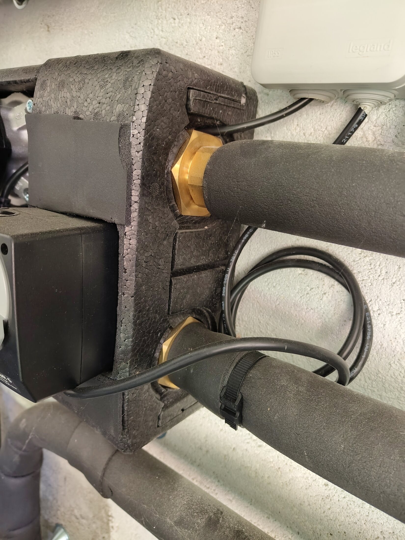
Two brass unions at rear of insulated group. Rear/right side · close-up.ConfirmedOpen full image ↗
secondary-pump-group/IMG_20260814_120619965_HDR.jpg

Secondary pump / mixer group

Two brass unions at rear of insulated group

View
Rear/right side · close-up
Evidence
This frame records the unions and local geometry. Their destinations are established by the wider household trace; this close-up alone does not establish direction.
Confidence
medium
Full image
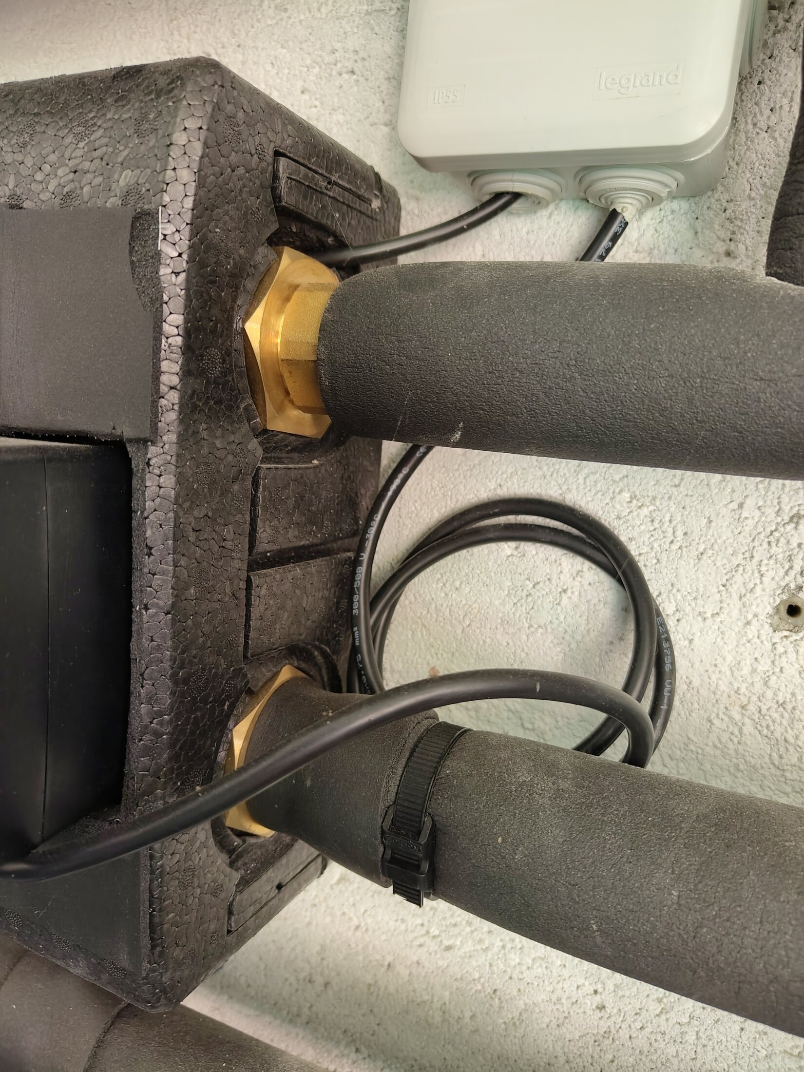
Two brass union connections behind the insulated group. Rear/right side · tighter close-up.ConfirmedOpen full image ↗
secondary-pump-group/IMG_20260814_120630761_HDR.jpg

Secondary pump / mixer group

Two brass union connections behind the insulated group

View
Rear/right side · tighter close-up
Evidence
This frame records the fittings and cable context. Use the wider route evidence for destinations; no flow direction is inferred from this angle.
Confidence
medium
Full image
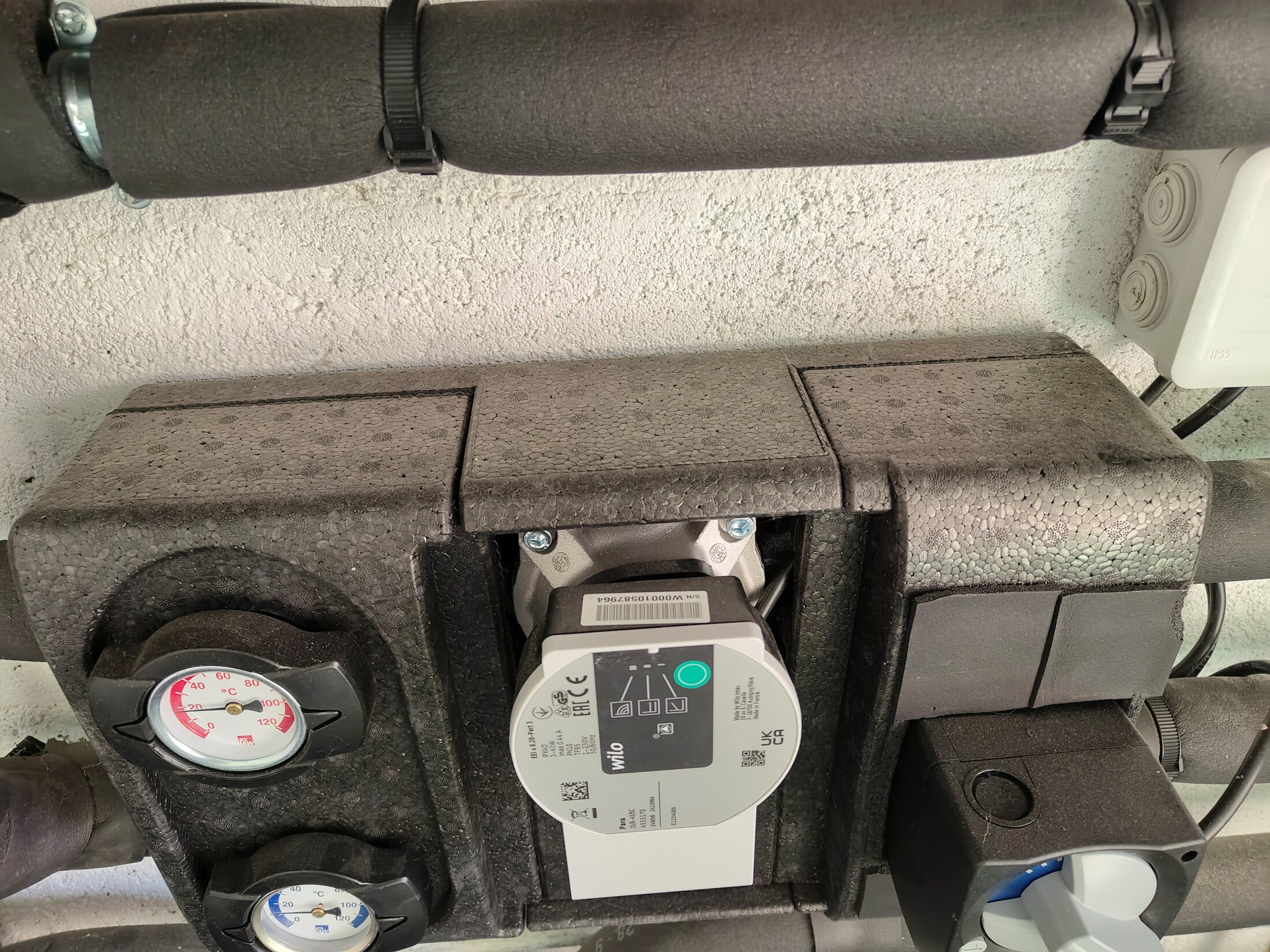
Thermometers, Wilo pump and upper pipe context. Upper context.ConfirmedOpen full image ↗
secondary-pump-group/IMG_20260814_120634924_HDR.jpg

Secondary pump / mixer group

Thermometers, Wilo pump and upper pipe context

View
Upper context
Evidence
Context view supports the surveyed SP connection positions. All four endpoint pairs are household-traced; their manufacturer functions and flow directions remain separate checks.
Confidence
high
Full image
Wilo circulator and SR 5 mixer labels. Front / angled close view.ConfirmedP2 · useful detailOpen full image ↗
secondary-pump-group/IMG_20260814_120641665_HDR.jpg

Secondary pump / mixer group

Wilo circulator and SR 5 mixer labels

View
Front / angled close view
Evidence
High-detail label view of the complete front assembly. A sharper companion view establishes Wilo mode Δp-c, curve III; the SR 5 actuator position remains a useful operating-state observation.
Verify
Record the SR 5 actuator position during known heating, natural-cooling and DHW states.
Confidence
high
Full image
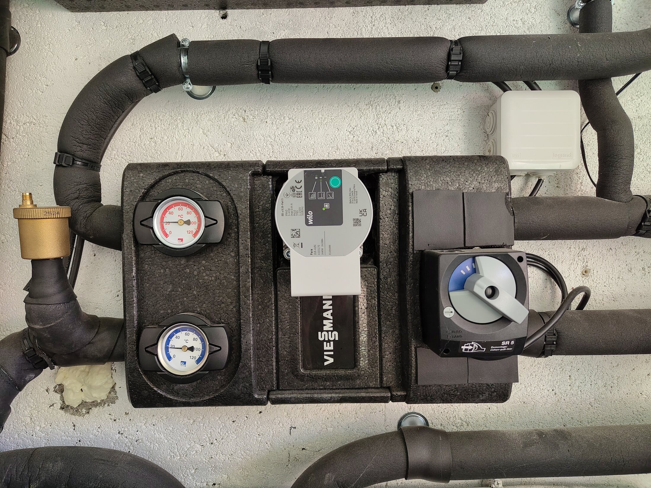
Complete secondary pump / mixer group. Straight-on context.ConfirmedP2 · useful detailOpen full image ↗
secondary-pump-group/IMG_20260814_120648491_HDR.jpg

Secondary pump / mixer group

Complete secondary pump / mixer group

View
Straight-on context
Evidence
Best straight-on context for thermometers, Wilo, SR 5 and automatic air vent. SP-TL/TR/BL/BR are app survey IDs for the four observed positions, not manufacturer labels.
Verify
Record thermometer readings and the SR 5 position during a known steady operating state; do not infer direction from red/blue colours.
Confidence
high
Full image
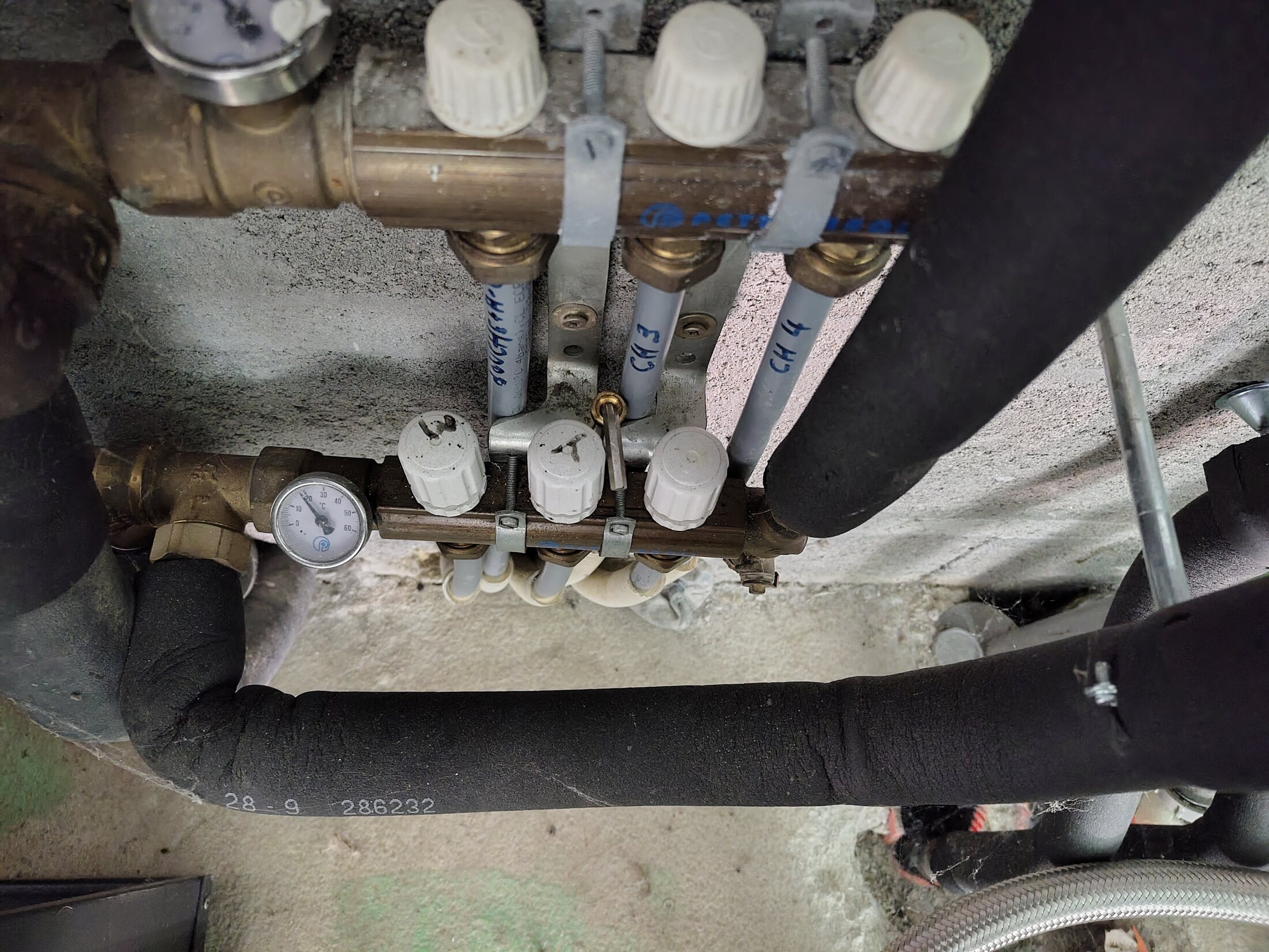
Lower manifold plus paired upstairs branches. Lower-floor manifold · overhead context.ConfirmedOpen full image ↗
secondary-pump-group/IMG_20260814_122132696.jpg

Buffer and lower manifold

Lower manifold plus paired upstairs branches

View
Lower-floor manifold · overhead context
Evidence
Household physical trace confirms SP-BL terminates at the lower header beside the gauge. At the outer-left edge, partly visible tees on both common pipes branch to the remote upper-floor manifold; exact flow/return assignment remains open.
Confidence
high
Full image
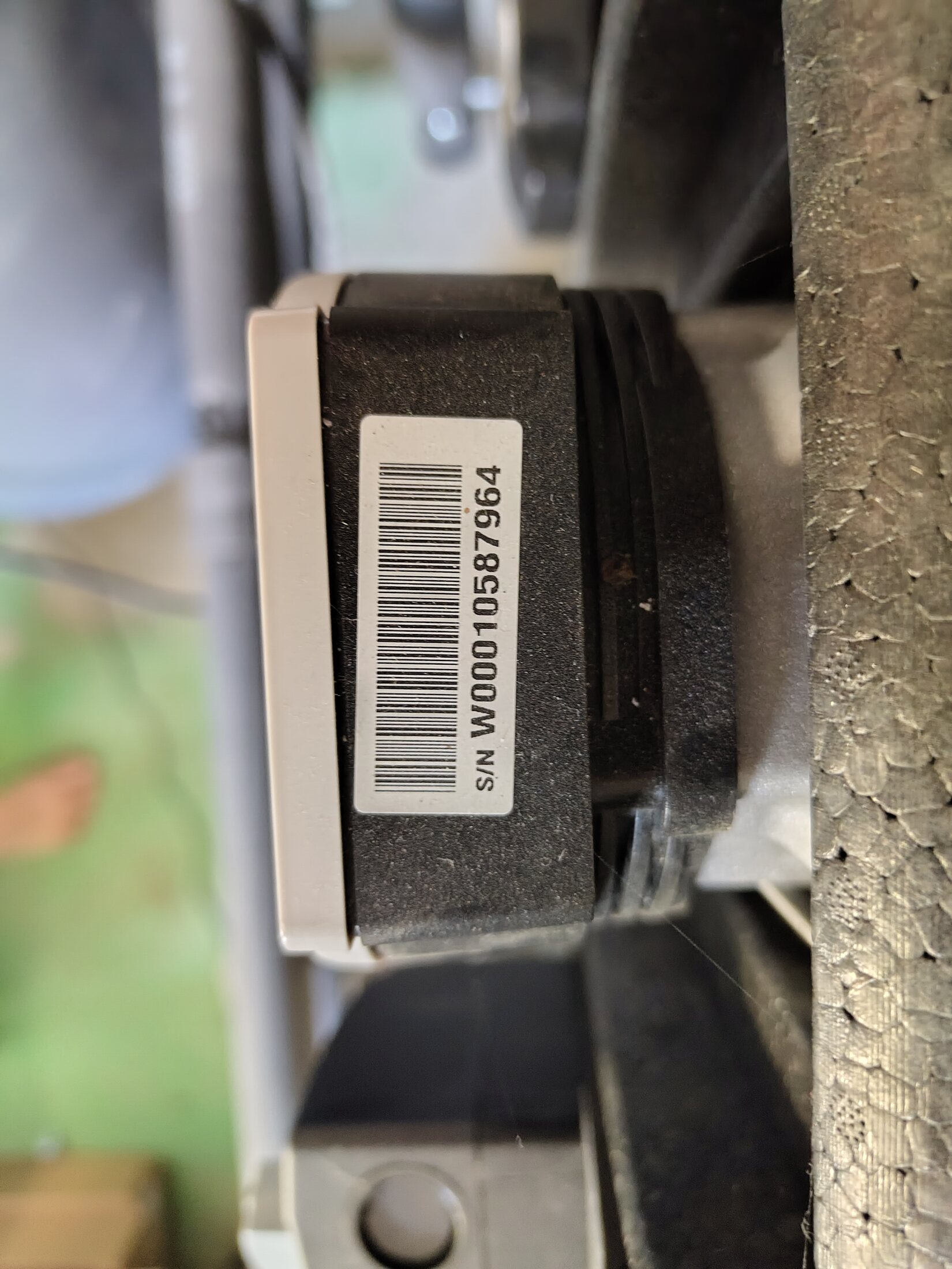
Wilo Para traceability markings. Pump face · serial/barcode close-up.Visible, route openOpen full image ↗
secondary-pump-group/IMG_20260814_151705914.jpg

Secondary pump / mixer group

Wilo Para traceability markings

View
Pump face · serial/barcode close-up
Evidence
The serial/barcode area is photographed but not transcribed because this view is not sharp enough for a reliable character-level reading.
Verify
No further photo is required for hydraulic understanding; retain as traceability evidence.
Confidence
medium
Full image
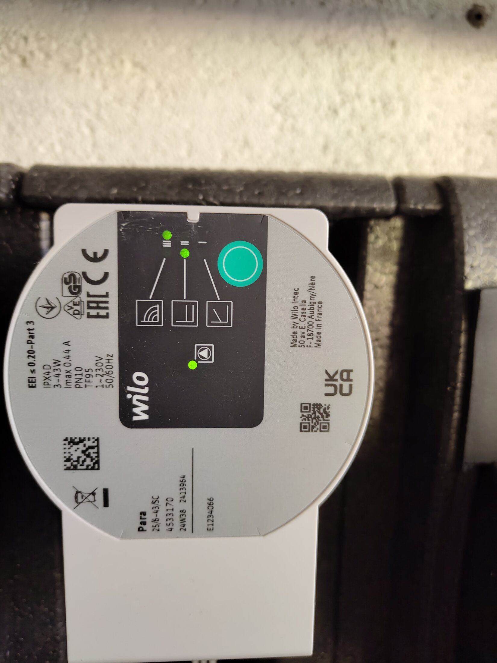
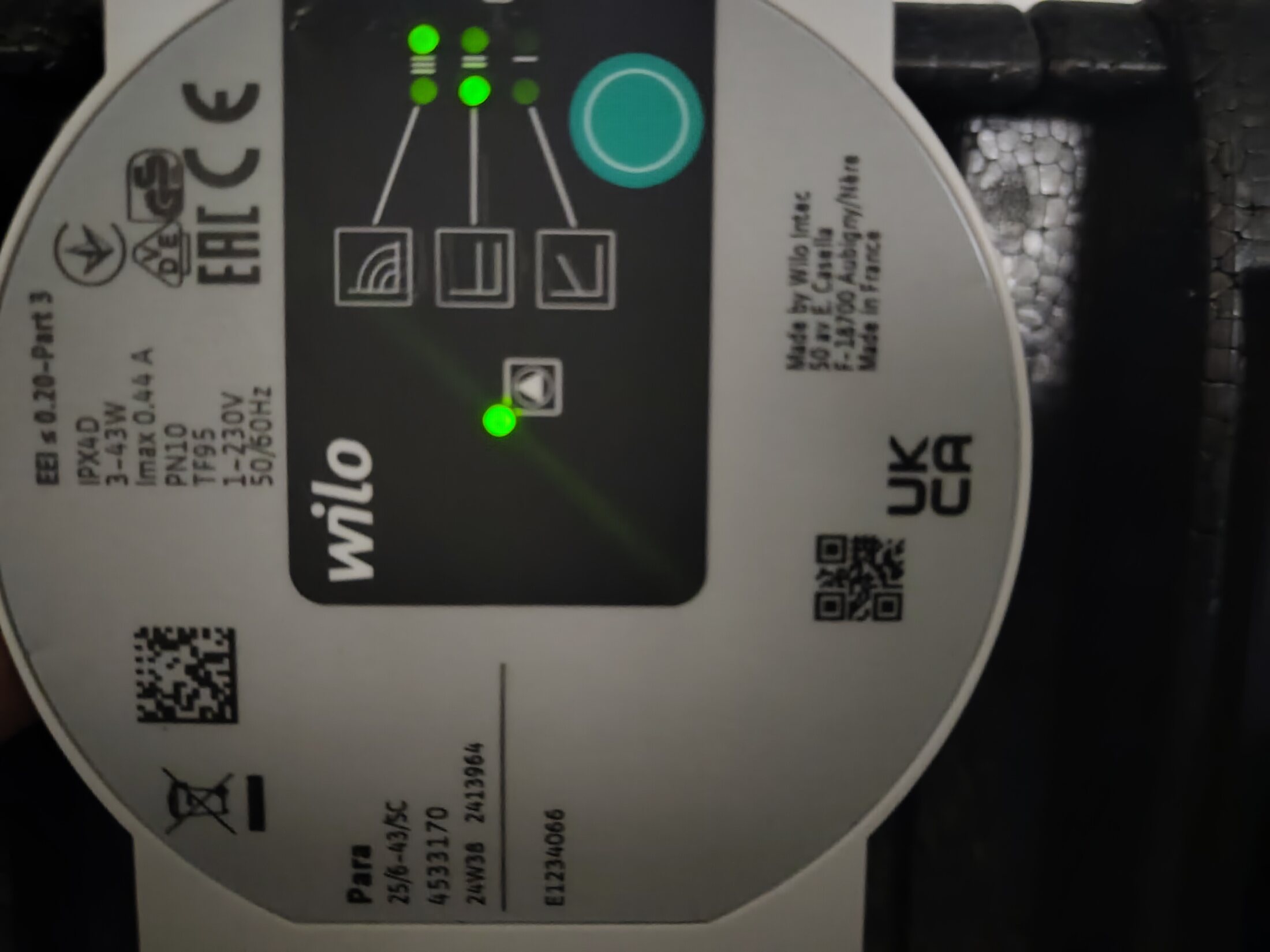
Wilo Para 25/6-43/SC · article 4533170. Pump face · model and live LEDs.ConfirmedP2 · useful detailOpen full image ↗
secondary-pump-group/IMG_20260814_151850299.jpg

Secondary pump / mixer group

Wilo Para 25/6-43/SC · article 4533170

View
Pump face · model and live LEDs
Evidence
Exact face records 3-43 W, Imax 0.44 A, PN10, TF95 and 1~230 V 50/60 Hz. The live display selects constant differential pressure, curve III, which Wilo recommends for underfloor heating and other circuits without a variable network curve.
Verify
Recheck the LEDs during heating and natural cooling to learn whether the setting is fixed or controller-dependent; this setting still does not reveal live flow.
Confidence
high
Full image
Installed hot-water outlet C toward house distribution. Floor-level trace.ConfirmedOpen full image ↗
dhw-pipework/IMG_20260814_152228271.jpg

Domestic hot-water pipework

Installed hot-water outlet C toward house distribution

View
Floor-level trace
Evidence
Household physical tracing follows the black-insulated DHW pipe from the heat pump into the floor, where it distributes into the house.
Confidence
high
Full image
DHW hot outlet C and adjacent cold/safety route. Top heat-pump connections.ConfirmedOpen full image ↗
dhw-pipework/IMG_20260814_152258407.jpg

Domestic hot-water pipework

DHW hot outlet C and adjacent cold/safety route

View
Top heat-pump connections
Evidence
The black-insulated C outlet is shown entering the heat pump. The adjacent potable-water connection runs to the photographed SFR safety group.
Confidence
high
Full image
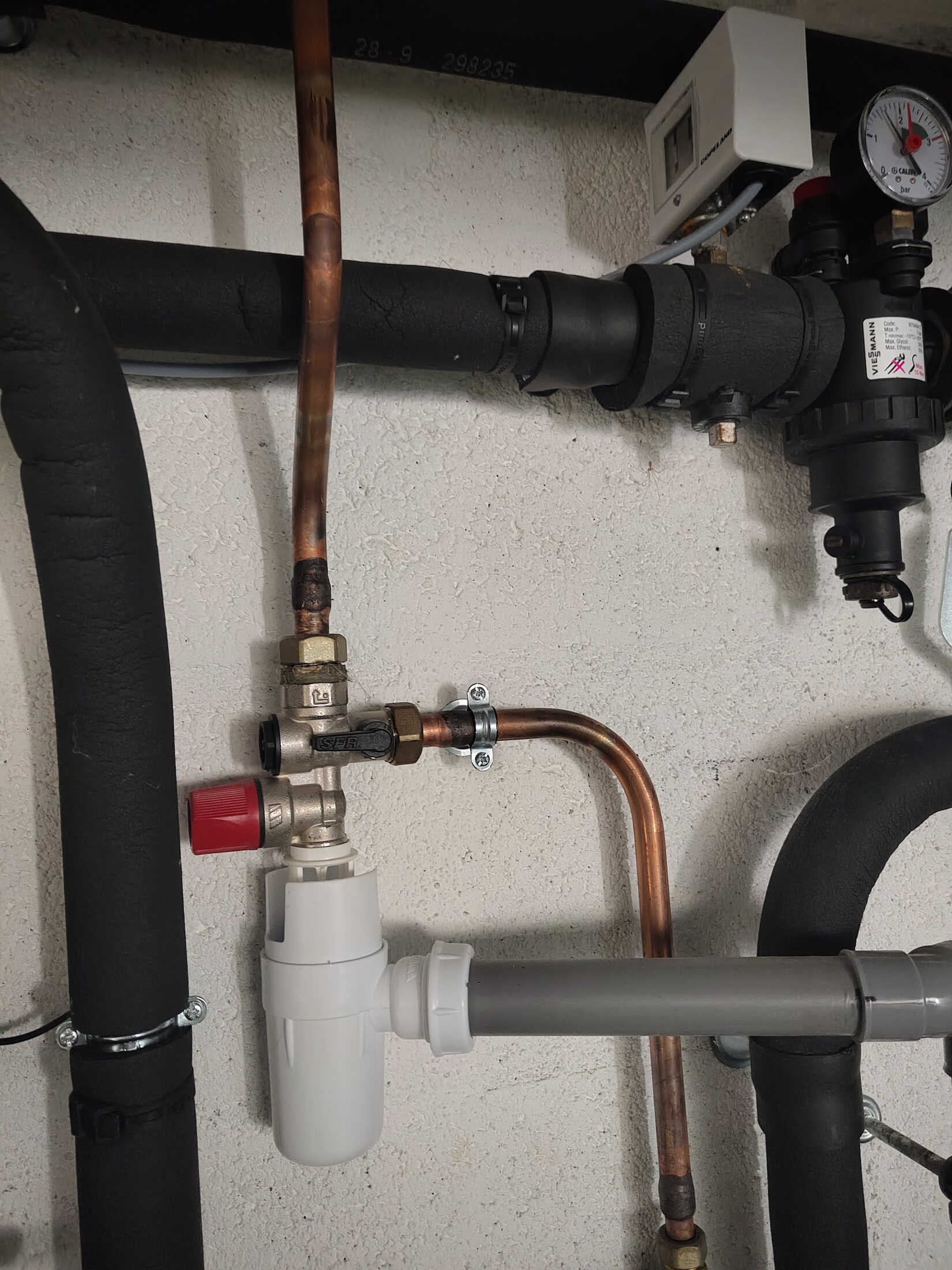
SFR DHW safety group and discharge siphon. Potable safety-group close-up.ConfirmedP2 · useful detailOpen full image ↗
dhw-pipework/IMG_20260814_152311923.jpg

Domestic hot-water pipework

SFR DHW safety group and discharge siphon

View
Potable safety-group close-up
Evidence
The SFR-marked brass body, red cap and white discharge siphon identify the potable cold-inlet safety assembly; it is not the source-side pressure group.
Verify
Record the exact model/pressure rating and final drain destination if visible.
Confidence
high
Full image
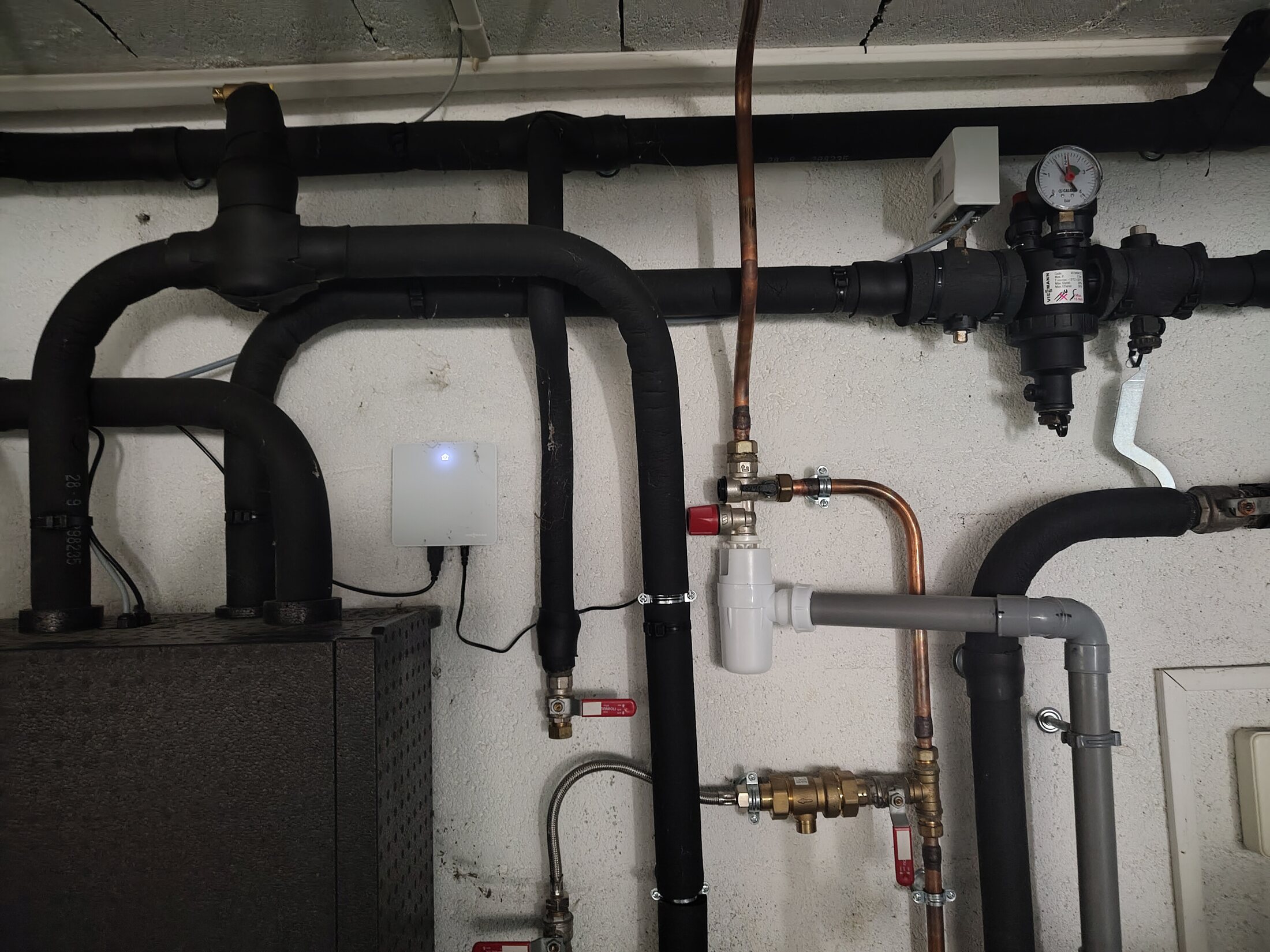
DHW safety group relative to NC-Box and source group. Wall context.ConfirmedOpen full image ↗
dhw-pipework/IMG_20260814_152319781.jpg

Domestic hot-water pipework

DHW safety group relative to NC-Box and source group

View
Wall context
Evidence
Context view separates the potable SFR assembly from the NC-Box at left and the black-insulated source pressure group above right.
Confidence
high
Full image
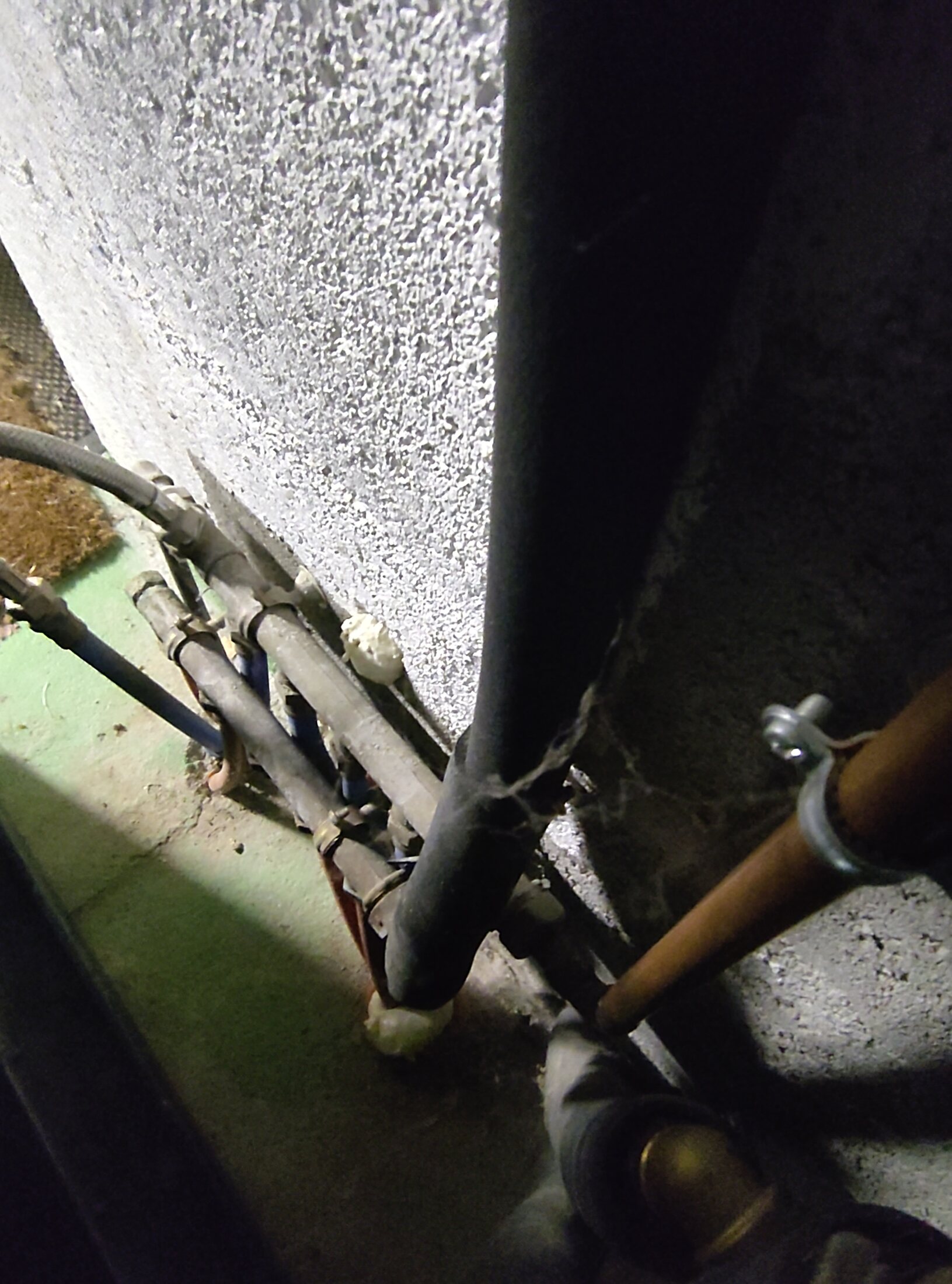
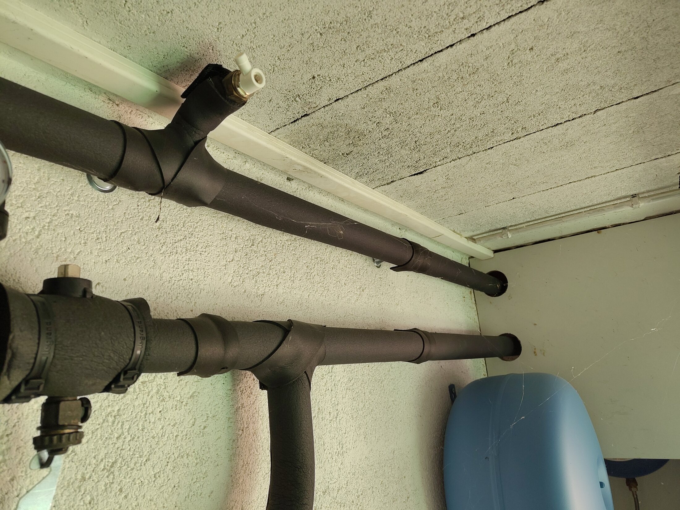
Two insulated source-side pipes with service / vent fittings. High wall · insulated pair.Visible, route openOpen full image ↗
source-pipework/IMG_20260814_121216033.jpg

Source-side pipework · route open

Two insulated source-side pipes with service / vent fittings

View
High wall · insulated pair
Evidence
The pipe pair and fittings are directly visible. Their assignment to a specific borehole and their flow/return direction remain untraced.
Confidence
high
Full image
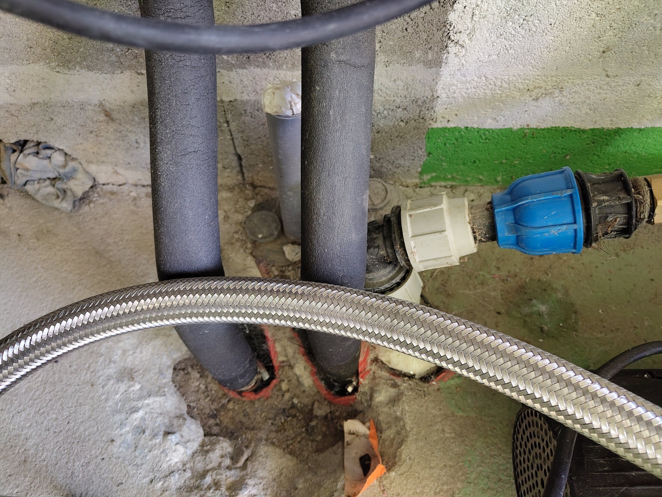
Two insulated pipes entering the plant-room floor. Floor entry · close context.Visible, route openOpen full image ↗
source-pipework/IMG_20260814_121221568.jpg

Source-side pipework · route open

Two insulated pipes entering the plant-room floor

View
Floor entry · close context
Evidence
The two floor penetrations are visible. Nearby well-water fittings are not used to infer a heating/cooling route, and the pipe pair is not assigned to a specific borehole from this image alone.
Confidence
high
Full image
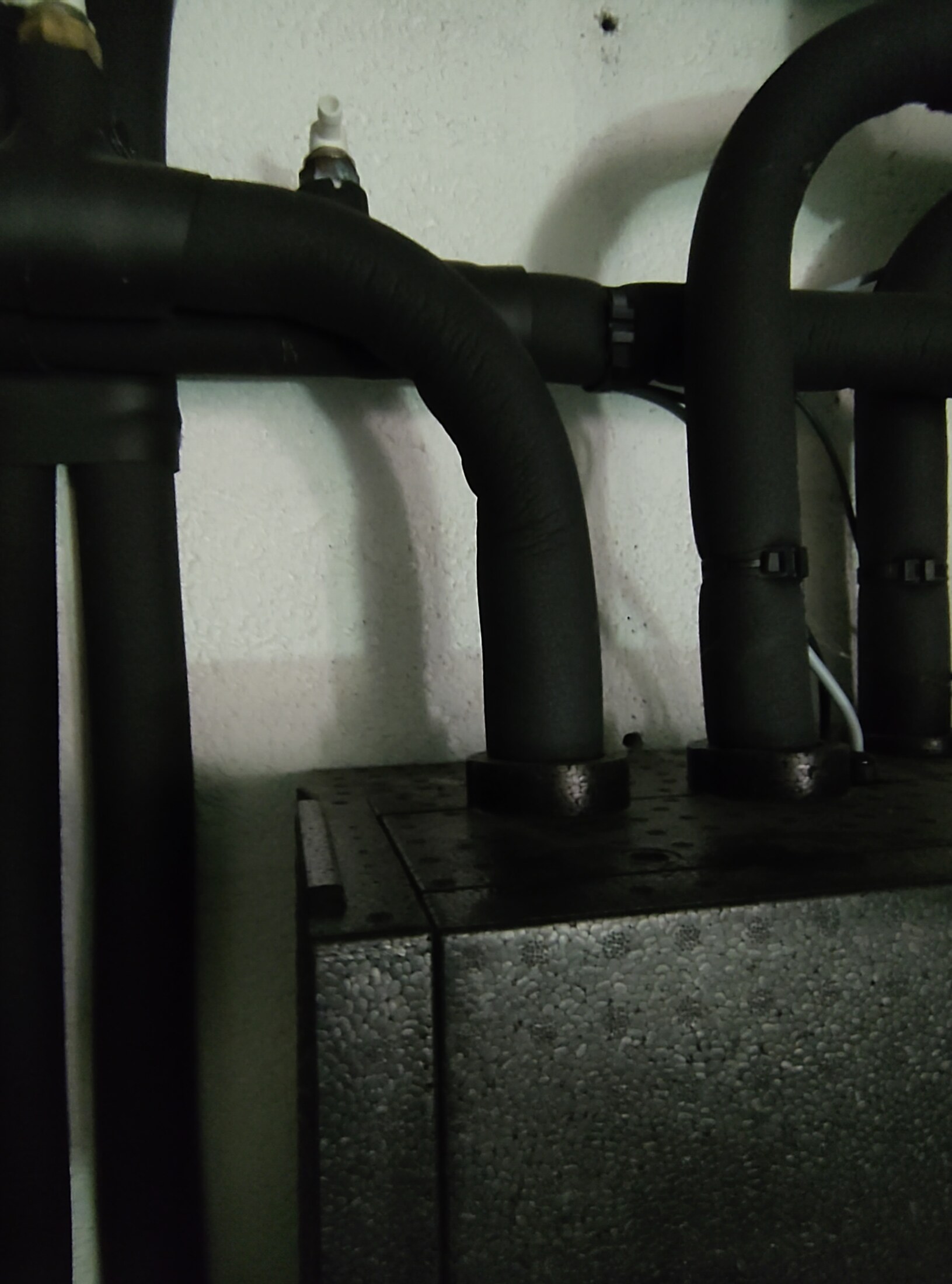
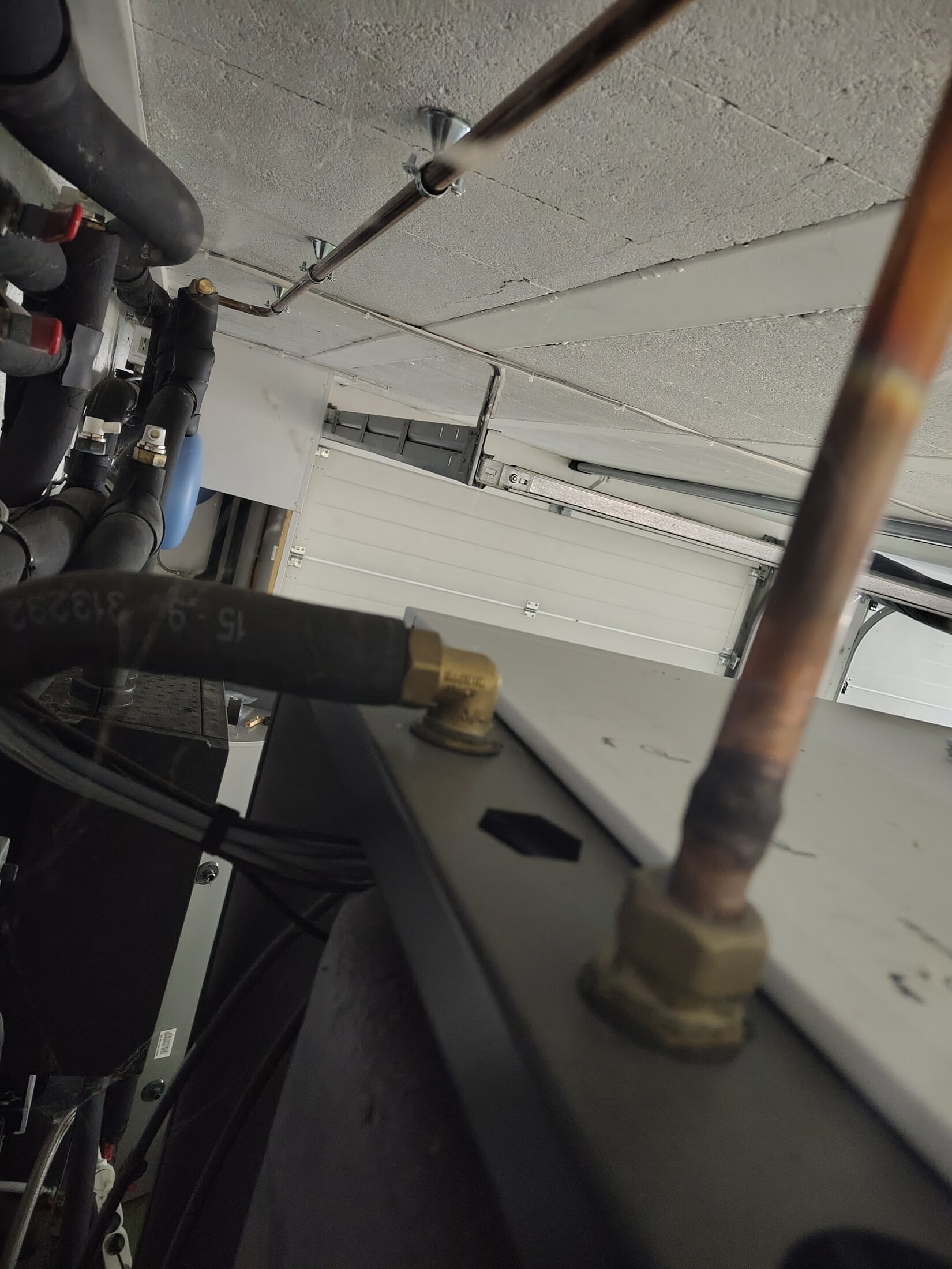
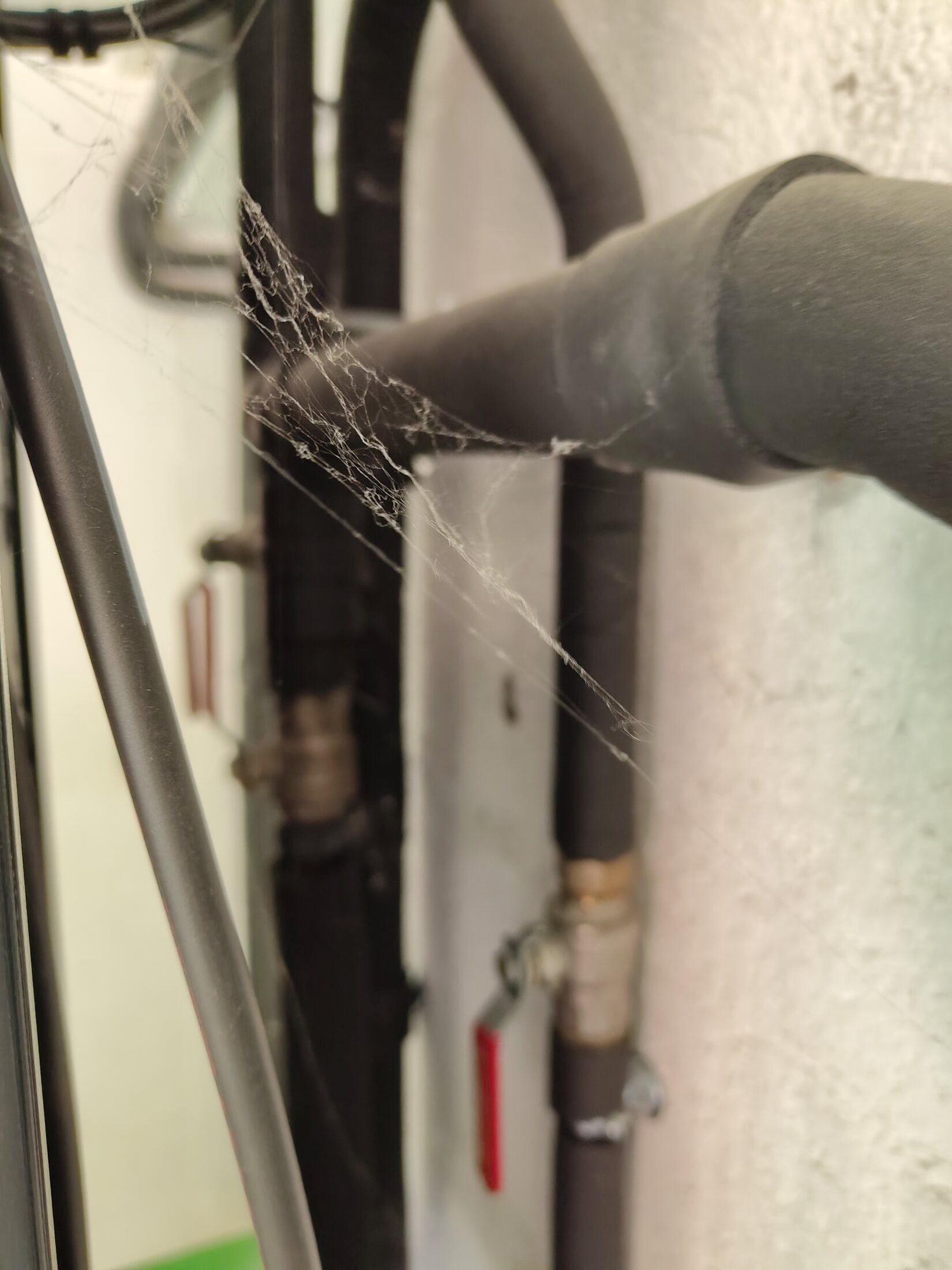
Partly obscured insulated pipe run. Behind equipment · restricted view.Needs reviewOpen full image ↗
source-pipework/IMG_20260814_121231825_HDR.jpg

Source-side pipework · route open

Partly obscured insulated pipe run

View
Behind equipment · restricted view
Evidence
The run is visible but the photograph does not expose enough endpoints to assign a route or function.
Confidence
medium
Full image
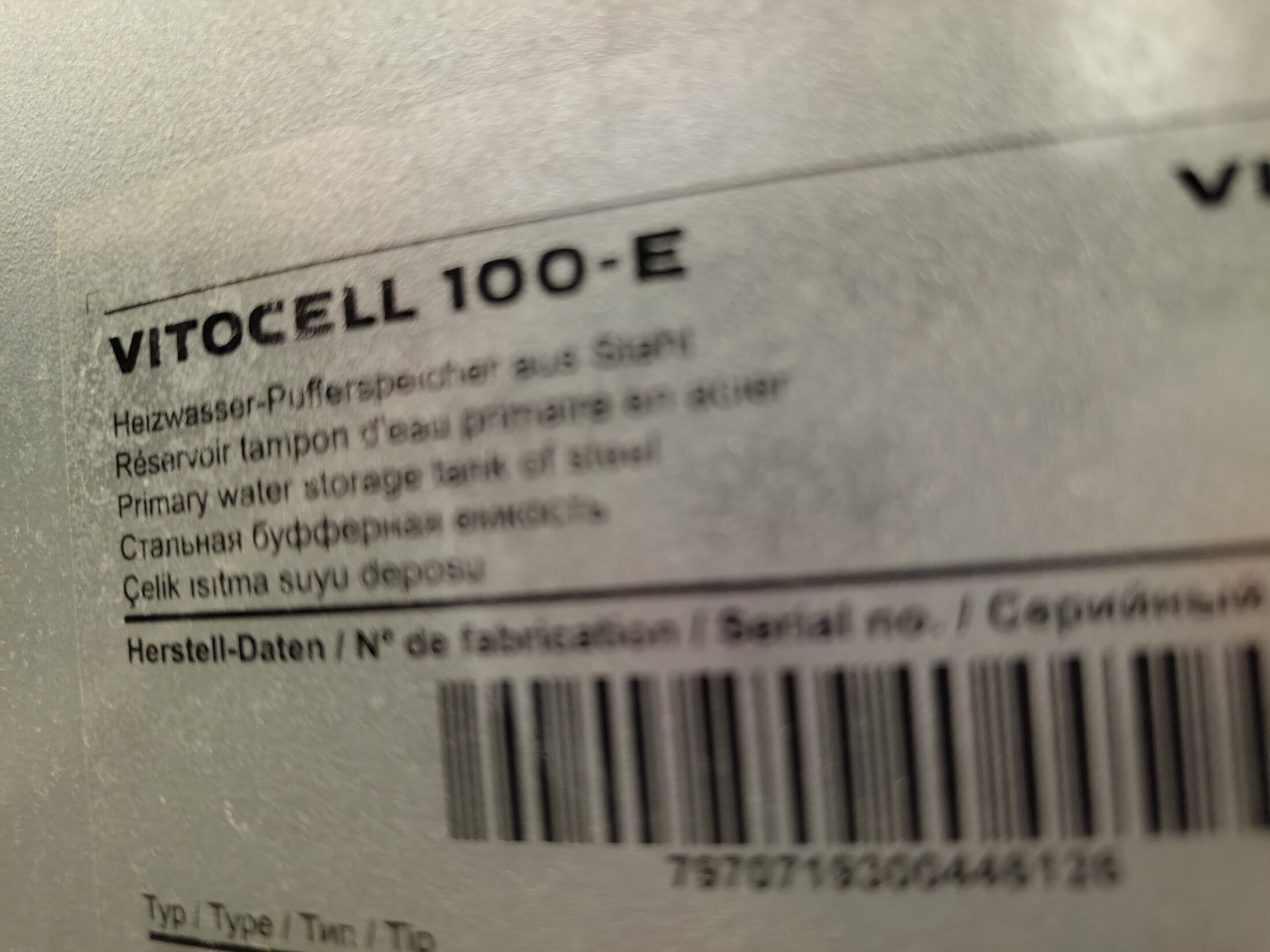
Viessmann Vitocell 100-E buffer label. Buffer type plate · close-up.ConfirmedP2 · useful detailOpen full image ↗
buffer-details/IMG_20260814_121320489.jpg

Buffer tank details

Viessmann Vitocell 100-E buffer label

View
Buffer type plate · close-up
Evidence
The product-family label is directly readable. Serial/type details should be transcribed from a sharper straight-on photograph before use.
Verify
Take a sharp, square photograph that resolves the exact type, serial and technical values.
Confidence
high
Full image
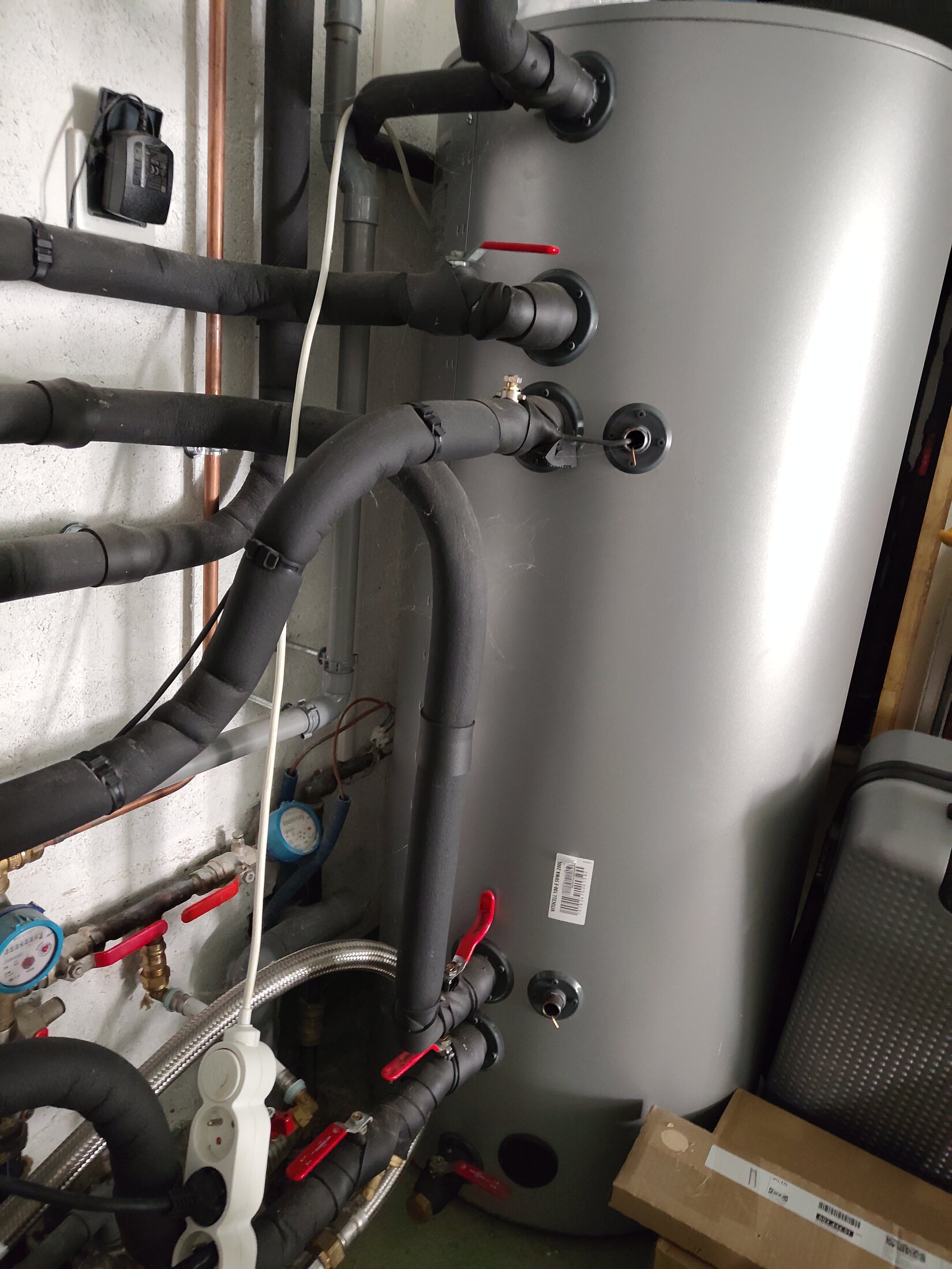
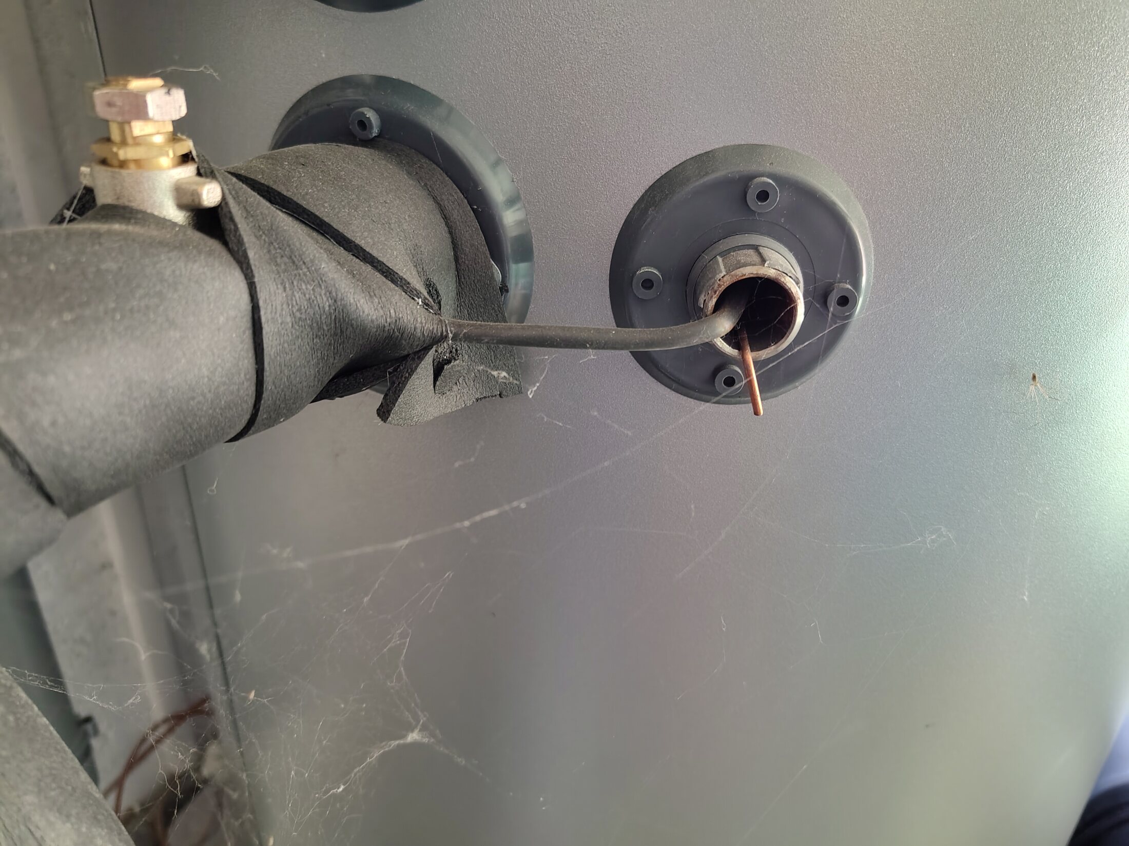
Installed buffer sensor pocket and probe lead. Buffer · BUF-3 close-up.ConfirmedP1 · topology blockerOpen full image ↗
buffer-details/IMG_20260814_121331987_HDR.jpg

Buffer tank details

Installed buffer sensor pocket and probe lead

View
Buffer · BUF-3 close-up
Evidence
Household-confirmed close-up shows the probe lead entering the small pocket immediately right of BUF-3 on the tank face, beneath the insulated pipe. The physical probe is confirmed; its Home Assistant entity and manufacturer pocket function remain unassigned.
Verify
Trace the probe cable to its wiring endpoint, record any label and correlate a live temperature change with the two HA buffer entities.
Confidence
high
Full image
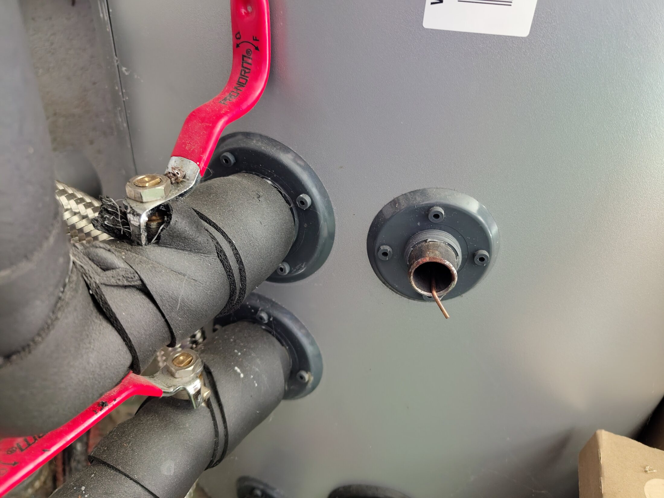
Sensor pocket beside adjacent connected buffer ports. Buffer · paired-port context.ConfirmedOpen full image ↗
buffer-details/IMG_20260814_121336238.jpg

Buffer tank details

Sensor pocket beside adjacent connected buffer ports

View
Buffer · paired-port context
Evidence
Wider context confirms the sensor pocket's height relative to the neighbouring buffer connections; exact entity and nozzle functions remain open.
Confidence
high
Full image